RCB-101-MW PC Software Operating Manual 9th Edition
Software License Agreement Before opening this product, read the software license agreement (hereinafter referred to as “Agreement”). This Agreement applies to the PC software that comes with this product (hereinafter referred to “Software”). By using this software, you are deemed to have agreed to the terms of this Agreement. You may not use this software if you do not agree to the terms of this Agreement.
Supported Models The PC software RCB-101-MW supports the following controller models of the specified versions and later. Table 1 List of Supported Models Model name RCP RCS E-Con RCP2 ERC Supported versions (For each model, all controllers of the specified version and later are supported.) V1.0.0.0 V3.0.0.0 V3.0.5.0 V4.0.0.0 V4.0.0.0 * Please check the controller model and the version of this application. If the controller is not supported by the software, the actuator may behave erratically.
A Word of Caution [1] This software is copyrighted by IAI Corporation (IAI). [2] The software and the manual can only be used upon the software license agreement. [3] We cannot assume responsibility for any damage or loss resulting from the use of this software or the manual. [4] Please note that the version or edition number printed on the face of this manual does not correspond to the software version number. [5] The content of this manual is subject to change without notice.
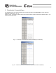
Table of Contents 1. Before You Begin ..................................................................................................................1 1-1 1-2 1-3 1-4 1-5 Items Supplied with This Software.............................................................................................1 What You Will Need (System Requirements) ............................................................................1 Installing the Software...................................................................
1. Before You Begin 1-1 Items Supplied with This Software Please check to make sure that the following items are included in your software package. [1] Operating manual [2] 1 CD containing the software [3] Software license agreement (explanation sheet) [4] External connection unit (PC cable with RS485 adapter) 1-2 What You Will Need (System Requirements) The following PC and peripherals will be necessary to run this software program.
[9] Serial port An RS232C serial port. (Only a 9-pin port is supported.) [10] Printer A printer compatible with the PC. 1-3 Installing the Software This software is run from the hard disk. This section explains how to install the software. [1] Insert the compact disk into the CD ROM drive. [2] Double-click Setup.EXE in disk 1. [3] The installation program will start. Follow the onscreen prompts to select the applicable installation options.
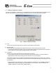
1-5 Setting of Application Window The “Setting of application” window (Fig. 1) is displayed only once after the software has been installed for the first time. In this window, set the information the software needs to communicate with the controller. Fig. 1 Setting of Application Window [1] Port From the list, select the serial port to be used to communicate with the controller. [2] Baudrate (bps) From the list, select the baudrate the software will use when communicating with the controller.
2. Checking for Connected Axes The software checks for connection all axes up to the axis specified in the Last axis # box of the “Setting of application” window (Fig. 1 or 7.5). After the check, “(Connecting)” will be shown for those axes whose connection has been confirmed, while “-” will be shown for all other axes. Fig. 2.1 Check for Connected Axes Window (Checking for Connection) Fig. 2.
3. Main Window Fig. 3.1 Main Window You can select the following items from the main menu or toolbar available in the main window (Fig. 3.1). 3-1 Operating from the Main Menu (1) File [1] [New] Create new position data. [2] [Open] Load position data or parameters from a file. [3] [Close] Close the active file. [4] [Send to Controller] (Available in the online mode) [Position Data] Write position data in a file to the controller. [Parameter] Write parameters in a file to the controller.
[5] [Backup] (Available in the online mode) [Save from Controller to File] Save all position data and parameters in the controller to a file. [Send from File to Controller] Send all position data and parameters in a file to the controller. [6] [Exit] Exit this application. (2) Position (Available in the online mode) [1] [Edit/Teach] Load position data from the controller for editing or use in teaching. [2] [Send to Controller] Transfer (write) edited position data to the controller.
[2] [Controller Setup] Reconnect: Reconnect the axes. If the software connects to multiple controllers linked by controller link cables, always select Reconnect after turning off and then on again the power to a connected controller to which the teaching pendant is not connected directly. Assign Axis Number: Set the axis number for an integrated controller. This menu item does not do anything for a separate controller. Reset Software: Reset (restart) the software.
3-2 Operations Using the Toolbar Buttons Fig. 3.2 Toolbar Buttons [1] New position data Same as clicking File, pointing to New, and then selecting Position Data. [2] Open file Same as clicking File, and then selecting Open. [3] Edit/teach position data Same as clicking Position, and then selecting Edit/Teach. [4] Edit parameters Same as clicking Parameter, and then selecting Edit. [5] Monitor Same as clicking Monitor, and then selecting Status. [6] CTR Error list Display the CTR Error list window.
Fig. 3.3 Toolbar Buttons [1] Cascade windows Same as clicking Window, and then selecting Cascade. [2] Tile windows vertically Same as clicking Window, and then selecting Tile Vertical. [3] Tile windows horizontally Same as clicking Window, and then selecting Tile Horizontal. 3-3 Tree View From the main menu, click Window, and then select Tree View. Fig. 3.4 Tree View [1] Axis No. 0 [ERC] Axis No. 8 [RCP] The axis number of each axis and the corresponding controller model are shown.
[2] Position data You can double-click this item to open the position data edit window. [3] Parameter You can double-click this item to open the parameter edit window. [4] Status monitor You can double-click this item to open the status monitor window. [5] CTR error list You can double-click this item to open the CTR error list window. [6] Velocity/Current You can double-click this item to open the velocity/current monitor window.
4. Selecting an Axis To perform any of the following operations, select the axis number of the target axis in the “Select axis number” window (Fig. 4.1). [1] Open the position data edit window in the online mode. (Note) [2] Send position data edited in the offline mode to the controller. (Note) [3] Open the parameter edit window in the online mode. (Note) [4] Send parameters edited in the offline mode to the controller. (Note) [5] Open the monitor window from the main window. [6] Save all data.
5. Editing Position Data You can edit position data in the online or offline mode. 5-1 Online Mode In this mode, data can be loaded from the controller for editing. (Fig. 5.1) Click Position and then select Edit/Teach from the main menu, or click in the toolbar. In the “Select axis number” window, select the axis number corresponding to the axis whose position data you want to edit. Refer to 4, “Selecting an Axis.
The operating methods of buttons and input controls available in this window are explained below. (1) Toolbar buttons Fig. 5.2 Toolbar in Position Data Edit Window [1] Save to file Save data to a file. [2] Send to controller Send (write) data to the controller. [3] Reload position data Reload position data from the controller and then refresh the displayed data.
[8] Switch display Change the display mode of the position data input area from normal to detail (or vice versa). (Fig. 5.14, Fig. 5.15) [9] Show monitor window Display the status monitor window of the axis you are currently editing. This window is the same as the one you can open by selecting Status from Monitor in the main menu of the main window. [10] Divide position data equally Clicking this button will display the window shown in Fig. 5.4. Set appropriate values in Start Position No.
The input fields of position data generated by the equal division function, other than Position and Comment, will be populated by the corresponding values for the position specified in Start Position No. The Comment field will be cleared. * The equal division function can also be implemented from the pop-up menu (Fig. 5.6) displayed by right-clicking the position data input area. Fig. 5.
(2) Current position/alarm code The current position of the axis you are editing (unit: mm) and the associated alarm code, if any, are shown. Fig. 5.7 Current Position/Alarm Code (3) Jogging/inching operation controls Select Jog or Inc. (by adding a check mark to the corresponding checkbox) and use the Fw (+)/Bw (-) buttons to move the axis. Select the jogging speed from “1,” “10,” “30,” “50” and “100” [mm/sec] using the track bar. In the inching mode, select the feed pitch from “0.03,” “0.10” and “0.
Clicking (step) will move the axis by one position, while clicking (continuous move) will cause the axis to move continuously by looping within the block of specified position data. Clicking again while the axis is moving continuously will stop the axis when it reaches the next position. Clicking will stop the axis (the axis will start decelerating the moment the button is clicked and continue to decelerate until it finally stops.
Checkbox: Axis: Position: Location: Step movement button: Continuous move button: Stop button: Example of use) The axes with a check mark in this box will move. The selectable checkboxes are those of axes whose point edit window is currently open. Axis number. Set a position number in one field. This position determines the movement range for each specified axis based on a routine similar to continuous movement, and the axis will move over the determined range.
(5) Program Just like positioning, this is also a test operation mode. In the program mode, however, you can set a desired sequence of movement. In the position number input area, enter position numbers (0 to 15) or “R” (a symbol specifying a repeat of the preceding numbers), and then click Start. Up to 17 steps can be specified, including “R.” If a blank field exists, all subsequent steps are considered invalid. All steps after “R” are also considered invalid. Position number input area Start button Fig.
[3] Alarm button This button lets you reset an alarm. Note that an alarm can be reset only when the servo is off and the cause of the alarm has been removed. While an alarm is present, a red lamp remains lit on the button. (7) Position data input area Enter position data in this area. Normally, you can enter in the Position, Speed, ACC and Comment fields. By switching to the detail mode by clicking the display switching button ( ), the Push, Pos.
5-2 Offline Mode When editing data after creating new data or loading data from a file, you are editing the data in the offline mode. In this mode, the screen controls relating to axis operation are grayed out, and only the toolbar and point data input area become active. Once data has been edited, you can save the data to a file or send it to the “connected” controller. * The Comment field can only be saved to a file. It cannot be saved to the controller.
6. Editing Parameters To load parameter data from the controller, click Parameter and then select Edit from the main menu, or click in the toolbar. In the “Select axis number” window, select the axis number corresponding to the axis whose parameters you want to edit. (Refer to 4, “Selecting an Axis.”) You can load data from the controller or a file and edit the loaded data. You can also print the loaded data. Edited data can be sent to the controller or saved to a file.
Depending on the controller model, a confirmation window (Fig. 6.2) may be displayed after parameters have been sent to the controller, asking if you want to restart the controller (reset the software). (This window appears only when the controller to which data has been written supports the software reset function. Refer to “Supported Models.”) Fig. 6.2 Controller Restart Confirmation Window • If you want to change the soft limits, set values corresponding to 0.3 mm outside of the desired effective range.
7. Monitoring You can monitor various statuses, controller error list, and velocity/current waveforms (only if the controller supports the function). 7-1 Status Monitor Window To monitor various statuses, click Monitor and then select Status in the main menu, or click in the toolbar. In the “Select axis number” window, select the axis number corresponding to the axis whose statuses you want to monitor. (Refer to 4, “Selecting an Axis.”) (Fig. 7.
7-2 Controller Error List To monitor the controller error list, click Monitor and then select CTR Error List from the main menu, or click in the toolbar. In the “Select axis number” window, select the axis number corresponding to the axis whose controller error list you want to monitor. (Refer to 4, “Selecting an Axis.”) Fig. 7.
7-3 Velocity/Current Monitor Window To monitor velocity/current, click Monitor and then select CTR Error List from the main menu, or click toolbar. In the “Select axis number” window, select the axis number corresponding to the axis whose velocity/current you want to monitor. (Refer to 4, “Selecting an Axis.”) The software will start monitoring velocity/current when is clicked. in the Monitor start button Rated current ratio checkbox Fig. 7.
(3) Toolbar Fig. 7.5 Toolbar [1] Save as Save the displayed current data and velocity data to a file (CSV format). * Only the range of data displayed in the data display area will be saved. * The saved file cannot be read in this application. [2] Print Print the displayed current and velocity data. [3] Monitor start button Start monitoring. [4] Monitor stop button Stop monitoring.
7-4 Setting of Application Window Click Setup from the main menu, and then select Application Setup. Fig. 7.6 Setting of Application Window [1] Port From the list, select the serial port to be used to communicate with the controller. [2] Baudrate (bps) From the list, select the baudrate the software will use when communicating with the controller. * The baudrate selected here is used only in the communication between this application and controller.
* The change will become effective once the application is restarted or the axes are reconnected. Fig. 7.
8. Version Information Fig. 8.1 Version Information [1] Application version The version of this application is shown. [2] Controller version The software version and manufacturing information of each connected controller are shown. (Manufacturing information may not be displayed depending on the controller type.
9. File Extensions Table 2 List of File Extensions Model name RCP RCS E-Con RCP2 ERC Position data file *.ptr *.ptr * pte *.ptr2 *.ptre Parameter file *.pmr *.prr *.pre *.pmr2 *.pmre Backup file *.bkr *.bur *.bue *.bkr2 *.
Change History Revision Date August 2011 Description of Revision 9th edition Change in software license agreement.
Manual No.: ME0107-9A (August 2011) Head Office: 577-1 Obane Shimizu-KU Shizuoka City Shizuoka 424-0103, Japan TEL +81-54-364-5105 FAX +81-54-364-2589 website: www.iai-robot.co.