Thin and Small ROBO Cylinder Mini Cylinder RCD Actuator Operation Manual First Edition Rod Type RA1D IAI America, Inc.
Please Read Before Use Thank you for purchasing our product. This Operation Manual explains the handling methods, structure and maintenance of this product, among others, providing the information you need to know to use the product safely. Before using the product, be sure to read this manual and fully understand the contents explained herein to ensure safe use of the product. The CD/DVD that comes with the product contains operation manuals for IAI products.
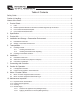
Table of Contents Safety Guide ............................................................................................................................ 1 Caution in Handling ................................................................................................................. 6 Names of the Parts .................................................................................................................. 7 1. Product Check .................................................................
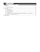
11. Appendix ......................................................................................................................... 28 11.1 External Dimensions............................................................................................................................28 12. Warranty.......................................................................................................................... 29 12.1 12.2 12.3 12.4 12.5 12.6 Warranty Period .....................................
Safety Guide “Safety Guide” has been written to use the machine safely and so prevent personal injury or property damage beforehand. Make sure to read it before the operation of this product. Safety Precautions for Our Products The common safety precautions for the use of any of our robots in each operation. 1 Operation Description Model Selection 2 Transportation 3 Storage and Preservation No.
No. 4 2 Operation Description Installation and Start Precautions (1) Installation of Robot Main Body and Controller, etc. � Make sure to securely hold and fix the product (including the work part). A fall, drop or abnormal motion of the product may cause a damage or injury. � Do not get on or put anything on the product. Failure to do so may cause an accidental fall, injury or damage to the product due to a drop of anything, malfunction of the product, performance degradation, or shortening of its life.
No. 4 Operation Description Installation and Start 5 Teaching 6 Trial Operation Precautions (4) Safety Measures � When the product is under operation or in the ready mode, take the safety measures (such as the installation of safety and protection fence) so that nobody can enter the area within the robot’s movable range. When the robot under operation is touched, it may result in death or serious injury.
No. 7 4 Operation Description Automatic Operation 8 Maintenance and Inspection 9 Modification 10 Disposal Precautions � Before the automatic operation is started up, make sure that there is nobody inside the safety protection fence. � Before the automatic operation is started up, make sure that all the related peripheral machines are ready for the automatic operation and there is no error indication.
Applicable Modes of IAI’s Industrial Robot The safety precautions are divided into “Danger”, “Warning”, “Caution” and “Notice” according to the warning level, as follows, and described in the Operation Manual for each model. Level Degree of Danger and Damage Symbol Danger This indicates an imminently hazardous situation which, if the product is not handled correctly, will result in death or serious injury.
Caution in Handling 1. Do not set speeds and accelerations/decelerations equal to or greater than the respective ratings. If the actuator is operated at a speed or acceleration/deceleration exceeding the allowable value, abnormal noise or vibration, failure, or shorter life may result. In the case of interpolated operation of combined axes, the speed and acceleration/deceleration settings should correspond to the minimum values among all combined axes. 2.
Names of the Parts In this Operation Manual, the left and right sides are indicated by looking at the actuator from the motor end, with the actuator placed horizontally, as shown in the figure below.
1. Product Check 1. Product Check If based on a standard configuration, this product consists of the items listed below. Caution: Check the packed items against the packing specification. Should you find a wrong model or any missing item, please contact your IAI dealer or IAI. 1.1 Parts No. 1 Name Actuator Model number Refer to “How to Read the Model Nameplate” and “How to Read the Model Number.
1.4 How to Read the Model Number Identification for IAI use only RA1D N : None S : 3m M : 5m X�� : Length specification R��: Robot cable I : Incremental 3 : 3W 2 1. Product Check RCD-RA1D-I-3-2-10-D3-S-** *1 D3 : DSEP *1 This may be displayed for the manufacturing reason. (This is not to indicate the manufacturing model code.
2. Specification 2. Specification (1) Maximum Speed The maximum speed of the actuator is limited to prevent resonance of the lead screw shaft by the motor speed limit. Be sure to observe the applicable maximum speed shown in the table below. Strokes and maximum speed limits (Unit: mm/s) Type RA1D Motor Type [W] Lead [mm] 3 2 Stroke [mm] Horizontal/ Vertical 10 20 Horizontal 30 300 Vertical (Note) For short strokes, the rated speed may not be achieved.
(5) Current Limit Value and Pressing Force Current Limit Value and Pressing Force 2. Specification Pressing Force (N) 7 6 5.98 5 4.99 4 4.01 3.02 3 2.04 2 1.05 0.41 1 0 0% 10% 20% 0.85 1.28 1.72 2.16 30% 40% 50% 60% Current Limit Value (%) 2.60 70% 80% Caution: (1) The relation of the pressing force and current limiting value is a reference. There will be a little variance in the actual pressing force. (2) If the current limiting value is low, the pressing force may largely vary.
3. Product Life 3. Product Life This actuator applies a lead screw and the plastic nut gets worn away. As the plastic nut is worn, the accuracy of the lost motion mainly gets worse. Based on the abrasion of the plastic nut and the degradation in the performance of the grease on the screw, the product life is determined as it is described below. (It is the value when an external guide and a free joint are used.
4. 4.1 Installation and Storage • Preservation Environment Installation Environment The actuator should be installed in a location other than those specified below. In general, the installation environment should be one in which an operator can work without protective gear. Also provide sufficient work space required for maintenance inspection. If the actuator is used in any of the following locations, provide sufficient shielding measures: � Where noise generates due to static electricity, etc.
5. 5.1 5. Transportation 5.1.1 Transportation Handling of Robot Handling the Packed Unit Unless otherwise specified, the actuator is shipped with each axis packaged separately. � Do not damage or drop. The package is not applied with any special treatment that enables it to resist an impact caused by a drop or crash. � Transport a heavy package with at least more than two operators. Consider an appropriate method for transportation.
5.2 Handling in Assembled Condition � When carrying the actuator, exercise caution not to bump it against nearby objects or structures. � Secure the rods to prevent sudden movement during transport. � If any end of the actuator is overhanging, secure it properly to avoid significant movement due to external vibration. � If the actuator assembly is transported without the ends being secured, do not apply an impact of 0.3G or more.
6. 6.1 Installation Installation of Main Unit � The installation bracket should possess enough stiffness, and also prevent vibration exceeding 0.3G from being applied to the main unit. � Have enough space for the maintenance work. � 6. Installation Install the main body in the clearance hole (�10) of a smooth plate of about 1 to 3mm in thickness and fix it. Both horizontal and vertical are available for the installation orientation. � The root of the male screw on the unit possesses (M10 × 1.
General-purposed products as shown below can be used for the foot bracket and flange bracket. Please contact directly to the supplier for the foot bracket and flange bracket. Foot brackets 6.2 SMC Co., Ltd. CJ-L016B CJ-F016B CKD Co., Ltd. P2-LS-16 P2-FA-16 6. Installation Foot brackets Flange brackets Flange brackets KOGANEI Co., Ltd. 1A-PBDA-16 3-PBDA-16 Attachment of Work Piece (Object to Transport) � Attach the work piece (object to transport) with using the male screw (M4 × 0.
6.3 Precaution in Installation 1) Keep a space for allocating the cable at the rear side of the motor side of the actuator. Also, attempt to make the cable exiting straight from the actuator. 50 or more r 0o R3 6. Installation 20 or more re mo 2) Prevent external force being applied on the body when installed. It may cause a risk of an operation failure or breakage.
7. Connecting with Controller Both for the controller itself and for the connection cable between the controller and RCD (this controller), use a dedicated IAI controller and dedicated connection cable. This section explains the wiring method for a single axis. � If the dedicated connection cable cannot be secured, reduce the load on the cable by allowing it to deflect only by the weight of the cable or wire it in a self-standing cable hose, etc., having a large radius.
When designing an application system, incorrect wiring or connection of each cable may cause unexpected problems such as a disconnected cable or poor contact. The following explains examples of prohibited handling of cables. � � � Do not cut and reconnect the cable to extend or shorten the cable. Use a robot cable for any section where the cable will flex. [For the bending radius, refer to “9. Motor • Encoder Cable”.] Provide a sufficient bending radius and prevent the cable from bending at the same point.
When fixing the cable, provide a moderate slack and do not tension it too tight. � Do not use spiral tube in any position where cables are bent frequently. Separate the I/O and communication lines from the power and drive lines. Do not wire them together in the same duct. � Duct I/O Line (Flat Cable, etc.) � If a cable track is used, use a robot cable and prevent the cable from getting tangled or kinked in the cable track or flexible tube.
8. 8.1 Caution for Operation� Load Applied to Actuator 8. Caution for Operation � RCD-RA1D actuator cannot accept the load from sides (radial load) or rotation torque. Applying these types of load may cause an operation failure, breakage of components or shortened life. Use a device such as the external guide. � Pay attention to the reaction force so it would not become the load from a side. Utilize a guide so it receives the side load. Pay attention to the direction of the reaction force.
8.2 External Force Applied in Thrust Directions � Do not attempt to apply an excessive external force on the rod. � Avoid applying an external force or impact that exceeds the allowable external force in the thrust directions. The allowable external force (maximum pressing force) is 6.0N. Thrust Directions 8.
9. 9.1 Motor • Encoder Cables Motor • Encoder Integrated Cable Connection L (30) (25) (25) (15) CN1 CN2 Connector : 1-1827863-1 Contact : 1827570-2 Connector : PADP-24V-1-S Contact SPND-002T-C0.5 (AWG26) SPND-001T-C0.5 (AWG22) Connection diagram CN1 1-1827863-1(AMP) 9. Motor • Encoder Cables Pin No.
9.2 Motor • Encoder Integrated Cables Robot Type CB-CA-MPA���-RB L (30) (25) (25) (15) CN1 (30) CN2 Connector : 1-1827863-1 Contact : 1827570-2 Connector : PADP-24V-1-S Contact SPND-002T-C0.5 (AWG26) SPND-001T-C0.5 (AWG22) Connection diagram CN1 1-1827863-1(AMP) Color BK(AWG22/19) WT(AWG22/19) BR(AWG22/19) GN(AWG22/19) YW(AWG22/19) RD(AWG22/19) OR(AWG25) GY(AWG25) WT(AWG25) YW(AWG25) RD(AWG25) GN(AWG25) BK(AWG25) BR(AWG25) BK(AWG25) BRAWG25) GN(AWG25) RD(AWG25) WT(AWG25) YW(AWG25) ― Pin No.
10. Maintenance Inspection 10.1 Inspection Items and Schedule Follow the maintenance inspection schedule below. It is assumed that the equipment is operating 8 hours per day. If the equipment is running continuously night and day or otherwise running at a high operating rate, inspect more often as needed. Start of work inspection 1-month inspection 3-month inspection 6-month inspection Every 6-month since 10.
10.4 Grease Supply 10.4.1 Grease to be applied on Rod (Sliding Surface) The following grease is applied when the product is shipped out from IAI factory. Rod (sliding surface) Sumico Lubricant Co., Ltd. Sumitec 308 Even though an equivalent type of grease can be purchased from other suppliers, please be very careful in selecting grease since an inappropriate choice may give an impact to the actuator life. Caution: Do not attempt to apply any grease other than poly � olefin synthetic grease.
11. Appendix 11.1 Rod Tip Nut 0.5 0.2 Stroke M.E S.E Home M.E 0 φ10H8 -0.022 0.2 φ5 26.6 (Attachment nut not shown) 13.3 0 0 12-0.2 Attachment Nut φ8.3 φ5.1 φM10×1.0 0 -0 .2 12-0.2 4 M4×0.7 φ1 External Dimensions 10 12 8 11. Appendix Stroke 10 20 30 28 8 L L 52 62 72 Mass [g] 47 51 55 220 61 ORG : Home M.E : Mechanical End S.
12. Warranty 12.1 Warranty Period 12.2 Scope of Warranty One of the following periods, whichever is shorter: � 18 months after shipment from IAI � 12 months after delivery to the location specified by the user � 2,500 hours after start of operation Our products are covered by warranty when all of the following conditions are met.
12.5 Conditions of Conformance with Applicable Standards/Regulations, Etc., and Applications (1) If our product is combined with another product or any system, device, etc., used by the customer, the customer must first check the applicable standards, regulations and/or rules. The customer is also responsible for confirming that such combination with our product conforms to the applicable standards, etc.
Change History Revision Date October 2011 Description of Revision First edition Change History 31
Manual No.: ME3721-1A (October 2011) Head Office: 577-1 Obane Shimizu-KU Shizuoka City Shizuoka 424-0103, Japan TEL +81-54-364-5105 FAX +81-54-364-2589 website: www.iai-robot.co.jp/ Technical Support available in USA, Europe and China Head Office: 2690 W.