ROBO Cylinder Linear Servo Type Rod Type Instruction Manual Third Edition RCL-RA1L, RA2L, RA3L IAI America, Inc.
Please Read Before Use Thank you for purchasing our product. This Instruction Manual explains the handling methods, structure and maintenance of this product, among others, providing the information you need to know to use the product safely. Before using the product, be sure to read this manual and fully understand the contents explained herein to ensure safe use of the product. The CD or DVD that comes with the product contains instruction manuals for IAI products.
Table of Contents Safety Guide············································································································ 1 Caution in Handling ································································································· 8 International Standards Compliances ······································································ 9 Names of the Parts ································································································ 10 1.
4. Operational Conditions ··················································································· 36 5. Maintenance Inspection·················································································· 41 6. External Dimensions······················································································· 42 7. Life·················································································································· 45 8.
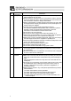
Safety Guide “Safety Guide” has been written to use the machine safely and so prevent personal injury or property damage beforehand. Make sure to read it before the operation of this product. Safety Precautions for Our Products The common safety precautions for the use of any of our robots in each operation. No.
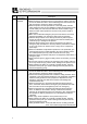
No. 2 2 Operation Description Transportation 3 Storage and Preservation 4 Installation and Start Description Ɣ When carrying a heavy object, do the work with two or more persons or utilize equipment such as crane. Ɣ When the work is carried out with 2 or more persons, make it clear who is to be the leader and who to be the follower(s) and communicate well with each other to ensure the safety of the workers.
No. 4 Operation Description Installation and Start Description (2) Cable Wiring Ɣ Use our company’s genuine cables for connecting between the actuator and controller, and for the teaching tool. Ɣ Do not scratch on the cable. Do not bend it forcibly. Do not pull it. Do not coil it around. Do not insert it. Do not put any heavy thing on it. Failure to do so may cause a fire, electric shock or malfunction due to leakage or continuity error.
No. 4 5 4 Operation Description Installation and Start Teaching Description (4) Safety Measures Ɣ When the work is carried out with 2 or more persons, make it clear who is to be the leader and who to be the follower(s) and communicate well with each other to ensure the safety of the workers. Ɣ When the product is under operation or in the ready mode, take the safety measures (such as the installation of safety and protection fence) so that nobody can enter the area within the robot’s movable range.
No. 6 7 Operation Description Trial Operation Automatic Operation Description Ɣ When the work is carried out with 2 or more persons, make it clear who is to be the leader and who to be the follower(s) and communicate well with each other to ensure the safety of the workers. Ɣ After the teaching or programming operation, perform the check operation one step by one step and then shift to the automatic operation.
No. 8 9 6 Operation Description Maintenance and Inspection 10 Modification and Dismantle Disposal 11 Other Description Ɣ When the work is carried out with 2 or more persons, make it clear who is to be the leader and who to be the follower(s) and communicate well with each other to ensure the safety of the workers. Ɣ Perform the work out of the safety protection fence, if possible.
Alert Indication The safety precautions are divided into “Danger”, “Warning”, “Caution” and “Notice” according to the warning level, as follows, and described in the Instruction Manual for each model. Level Degree of Danger and Damage Symbol This indicates an imminently hazardous situation which, if the Danger product is not handled correctly, will result in death or serious injury.
Caution in Handling 1. Ensure use of the product in the specified conditions, environments and ranges. Operation out of the specified conditions could cause a drop in performance or malfunction of the product. 䎃 2. Do not conduct any treatment or operation that is not stated in this instruction manual.䎃 䎃 3. For the wiring of the controller and actuator, use the IAI product.䎃 䎃 4. Do not attempt to establish the settings for the speed and acceleration/deceleration above the allowable range.
International Standards Compliances This actuator complies with the following overseas standard. Refer to Overseas Standard Compliance Manual (ME0287) for more detailed information.
Names of the Parts In this manual, the right and left sides of the actuator are expressed in the way it is placed horizontally as shown in the figure below, and is looked at from the motor side.
1. Specifications Check Checking the Product 1. Specifications Check 1.1 The standard configuration of this product is comprised of the following parts. See the component list for the details of the enclosed components. If you find any broken or missing parts, contact your local IAI distributor. 1.1.1 Components No. 1 Name Main Unit Model number Quantity Refer to “How to Read the Model Nameplate” and “How 1 to Read the Model Number.
1. Specifications Check 1.1.3 How to Read the Model Nameplate MODEL RCL-RA1L-I-2-N-25-A1-P Model Serial Number 1.1.4 SERIAL No.
1.2 Specification 1.2.1 Speed Type RA1L RA2L RA3L 1. Specifications Check Maximum speed [mm/s] 300 340 450 1.2.2 Relationship between Transportable Weight and Acceleration Speed The acceleration is determined by the transported weight and the duty. From the table below, determine the acceleration from Continuous Operation (Duty 100%) when the duty is over 70% and up to 100%, and Duty 70% or less when it is 70% or below. Type RA1L RA2L RA3L Max. Acceleration Speed [G] 0.1 0.3 0.
1.2.3 Rated Thrust and Transient Maximum Thrust 1. Specifications Check Type RA1L RA2L RA3L Rated Thrust [N] 2.5 5 10 Transient Maximum Thrust [N] 10 18 30 1.2.4 Encoder Resolution 0.042mm 1.2.5 No. of Encoder Pulses RA1L RA2L RA3L 715 855 1145 1.2.6 Positioning Repeatability ±0.1mm * It does not include the consideration of time-dependent change as it is used. 1.2.7 Relationship between Current Limiting Value and Pressing Force [Refer to 4.
1.3 Option Brake (with brake box) (Model No. : B) This is a function to hold the rod so it would not drop when the power or the servo is turned OFF in the condition that the actuator is installed in the vertical orientation. It is to be used to avoid damaging the attached objects by the rod being dropped. 1.3.2 Brake (with no brake box) (Model No.
1.4 Motor • Encoder Cables 1. Specifications Check 1.4.1 Motor • Encoder Integrated Cables (For AMEC, ASEP) CB-APSEP-MPAƑƑƑ Mechanical side Electric wire color Black White Brown Green Yellow Red Orange Gray White Yellow Red Green Black Brown Black Brown Green Red White Yellow shield 16 Signal name U V W – – – BK+ BKA+ AB+ BZ+ ZLS+ LSGNDLS VPS VCC GND – FG Controller side Pin No. Pin No.
1.4.2 Motor • Encoder Integrated Cables (with brake cable) (For AMEC, ASEP) CB-APSEP-MPBAƑƑƑ Electric wire color Black White Brown Green Yellow Red Orange Gray White Yellow Red Green Black Brown Black Brown Green Red White Yellow shield Brown Blue 1. Specifications Check Connected to the Brake Box 500±20 Signal name Pin No. Pin No.
1.4.3 Motor • Encoder Integrated Cables (For ACON, ASEL) 1. Specifications Check CB-ACS-MPAƑƑƑ (Front View) (Front View) Mechanical side Electric wire color Red Yellow Black Yellow (Redx) Yellow (Bluex) Pink(Redx) Pink(Bluex) White(Redx) White(Bluex) Orange(Redx) Orange(Bluex) Gray(Redx) Gray(Bluex) Orange (Red㨯continuous) Orange (Bluexcontinuous) Gray (Redxcontinuous) Gray (Bluexcontinuous) shield 18 Signal name U V W – Controller side Pin No. Pin No.
1.4.
2. Installation 2. Installation 2.1 Transportation [1] Handling of the Robot Unless otherwise specified, the actuators are packaged individually. (1) Handling the Packed Unit y Do not damage or drop. The package is not applied with any special treatment that enables it to resist an impact caused by a drop or crash. y An operator should never attempt to carry a heavy package on their own. Also, use an appropriate way for transportation.
[2] Handling in the Assembled Condition This is the case when the product is delivered from our factory under a condition that it is assembled with other actuators. The combined axes are delivered in a package that the frame is nailed on the lumber base. The rods are fixed so they would not accidently move. The actuators are also fixed so the tip of it would not shake due to the external vibration. (2) How to Handle after Unpackaged y Fix the rod(s) so they would not accidently move during transportation.
2.2 Installation and Storage • Preservation Environment [1] Installation Environment 2. Installation The actuator should be installed in a location other than those specified below. In general, the installation environment should be one in which an operator can work without protective gear. Also provide sufficient work space required for maintenance inspection.
2.3 How to Install This chapter explains how to install the actuator on your mechanical system. 2.3.1 General Rules on Installation Sideway installation { 2.
2.3.2 [1] Installing the Main Body Mounting Method 2. Installation Fixation to a mating component with a profile of hole since the body is in a cylindrical profile. φd Type RA1L RA2L RA3L B A Caution label Dimensions for Body Attachment O.D. of Pipe Pipe fixable range A Id (tolerance) 16 (0/-0.1) 90 20 (0/-0.1) 115 25 (0/-0.1) 164 Available range for screw fixing type B 30 40 55 Recommended Fixing Method Clamping (split clamp) Clamp with a profile of hole that suits the pipe.
Pipe Clamping Force (Reference value) Type Clamping force (Reference value) RA1L 1,00 [N] (100kg) or less RA2L 1,500 [N] (150kg) or less RA3L 2,000 [N] (200kg) or less Caution: With excessive force to tighten the pipe, the pipe may get deformed, which may result in an operation error or malfunction. Other Methods to Attach When Using Fixing Screws (set screws); When using the fixing screws, deformation is big in spots where the screws are touching the actuator compared to clamping.
[2] Mounting Bracket As an attachment bracket, the following general-purposed products can be used. Please contact directly to the supplier for each bracket. 2. Installation (1) Shaft Bracket Manufacturer : IWATA MFG.CO.,LTD. zRA2L Model Number : B20CP4 φ 48 33 28 φ 44 zRA1L Model Number : B16CP4 M4 bolt 12 M4 bolt 14.2 12 14.2 38 φ 53 zRA3L Model Number : B25CP4 M4 bolt 12 14.2 (2) Maru-Pijon Manufacturer : MIYOSHI PIJON CO.,LTD.
Shaft Holder Manufacturer : MISUMI Corporation 51 25 2. Installation 45 zRA2L Model Number : SHKSBT20 25 zRA1L Model Number : SHKSBT16 15 30 22 M5 bolt 24 40 32 M6 bolt zRA3L Model Number : SHKSBT25 30 58 (3) 24 40 32 M6 bolt Caution: Make sure to follow the specified tightening torque when clamping the body. Not doing so may damage the actuator.
2.3.3 Attachment of Transported Objects 2. Installation y Attach a transported item on the threaded area on the tip of the rod. Keep in mind of the incomplete thread. y When tightening, hold two faces with an open-end wrench so torque would not be applied on the rod. Applying excessive torque to the rod may damage the components inside. y The material of the rod is aluminum. Tighten the Enclosed nut with the Recommended tightening torque described below.
3. Connecting with the Controller As the connection cable for the controller and the actuator, use the IAI dedicated controller and dedicated connection cable. This section, explains how to layout wires for a single axis. Please consult with IAI if you require a different kind of cable than the one supplied.
[Connecting with the ACON and ASEL Controller] 3. Connecting with the Controller Dedicated Connection Cable (connects controller and RCL) r=84mm or more (Movable Use) r=42mm or more (Fixed Use) Dedicated Controller ACON ASEL Dedicated cables x Motor • Encoder Integrated Cables CB-ACS-MPAƑƑƑ x Motor • Encoder Integrated Cables (with brake cable) CB-ACS-MPBAƑƑƑ ƑƑƑ shows the cable length. The max. length should be 10m.
3.1 Brake Box Installation for Brake-Equipped Type Attach the brake box RCB-110-RCLB-0 for brake-equipped type. 3.1.1 Brake Box RCB-110-RCLB-0 (1.8) (1.8) 65 48 8.5 45 50.5 56 3 2.75 25 LEDs display •Green:BK RLS In brake release •Yellow:RLS SIG Output of the brake release signal Power / RDY Output Connector 2-φ3.
3.1.2 Procedures to Connect and Start Brake Box 1) Shown below are examples for how to connect to the ACON Controller and the ASEP Controller. (The procedures to connect it are the same as the ACON Controller for the AMEC, MSEP Controllers, ASEP Controller and the ASEL Controller.) Perform the connection following the examples below. 3.
Warning: For wiring, please follow the warnings stated below. When constructing a system as the machinery equipment, pay attention to the wiring and connection of each cable so they are conducted properly. Not following them may cause not only a malfunction such as cable breakage or connection failure, or an operation error, but also electric shock or electric leakage, or may even cause a fire. • Use dedicated cables of IAI indicated in this Instruction manual.
3. Connecting with the Controller • Do not pull the cable with a strong force. • Pay attention not to concentrate the twisting force to one point on a cable. • Do not pinch, drop a heavy object onto or cut the cable. • When a cable is fastened to affix, make sure to have an appropriate force and do not tighten too much. Do not use spiral tube in any position where cables are bent frequently.
• PIO line, communication line, power and driving lines are to be put separately from each other and do not tie them together. Arrange so that such lines are independently routed in the duct. Duct I/O lines (flat cable) Follow the instructions below when using a cable track. • If there is an indication to the cable for the space factor in a cable track, refer to the wiring instruction given by the supplier when storing the cable in the cable track.
4. Operational Conditions 4.1 Acceleration of the Setting 4. Operational Conditions The acceleration is determined by the transported weight and the duty. The graphs below show the upper limit for the acceleration against the transported weight and the duty. Set the acceleration to a value of Continuous Operation Available (100%) when the duty is over 70% and up to 100%, and set it to a value of 70% when it is 70% or below.
4.2 Reference for Cycle Time The graph below shows the cycle time in each acceleration pattern in maximum velocity. Take this as a reference for the operation time. 0.50 0.45 0.40 0.35 0.1G 0.5kg 0.3G 0.5kg 0.5G 0.5kg 1G 0.25kg 0.30 0.25 4. Operational Conditions Time [s] RA1L Cycle Time 1.5G 0.15kg 2G 0.1kg 0.20 0.15 0.10 0 5 10 15 20 25 Setting speed : 300mm/sec Movement distance [mm] Installation posture : Horizontal Time [s] RA2L Cycle Time 0.55 0.50 0.45 0.40 0.35 0.30 0.25 0.20 0.
4.3 Setting of Current Limiting Value at Pressing Operation When having a pressing operation, set up the current limiting value which determines the pressing force. The graph below shows the current against the pressing force. Take this as a reference for when making an adjustment to the pressing force. There is no limit to the pressing duration. Continuous pressing can be performed. 4.
It is necessary to consider the influence of the weight of movable part as shown in the figures below when installing in vertical orientation. Horizontal Vertical Downward pressing Vertical Upward pressing Weight of movable part m Pressing force = Thrust F=f Pressing force = Thrust + Weight of Movable Part F=f+m Pressing force = Thrust – Weight of Movable Part F=f–m Weight of Movable Part unit : [N] Type Weight of Movable Part RA1L 0.5 RA2L 1 RA3L 1.8 39 4.
4.4 Vibration • Resonance Noise Control 4. Operational Conditions There may be a case that vibration or resonance noise is generated as an impact of load weight, operational condition, condition of installation or mechanical stiffness. In such a case, the vibration or resonance noise can be controlled by increasing the torque filter time constant (parameter) shown below. Note that increasing this value to much may sacrifice the stableness of controllability.
5. Maintenance Inspection 5.1 Inspection Items and Schedule Follow the maintenance inspection schedule below. It is assumed that the equipment is operating 8 hours per day. If the equipment is running continuously night and day or otherwise running at a high operating rate, inspect more often as needed. After 3 years of operation, or upon reaching 5,000 km in traveled distance Every year thereafter 5.2 External visual inspection { { { { { 5.
6. External Dimensions RCL-RA1L without brake type 5.5 (Width across flats) 6.1 10 4 M4 × 0.7 (Effective Thread Depth 8) Stroke 25 3.2 8.1 200 SE ME Home ME 1 1 186 (18) 14 7 (114.5) φ16 φ6 0 -0.1 (R od dia me ter ME : Mechanical end SE : Stroke End Weight : 0.2 [kg] ) RCL-RA1L equipped with brake (option) 5.5 (Width across flats) 6.2 (φ7) 6. External Dimensions Enclosed nut M4×0.7 (Class 1) 4 (16) 10 (27.6) M4 (Effective Thread Depth 8) Enclosed nut M4 (Class 1) 8.1 3.
RCL-RA2L without brake type 7 (Width across flats) 6.3 12 5 M5 × 0.8 (Effective Thread Depth 8) Stroke 30 9.2 236 SE 4 Home ME ME 1 17 (22) 219 8 (140) φ 20 0 1 -0. φ 8 (Ro d dia 6. External Dimensions 1 me (φ7) Enclosed nut M5×0.8 (Class 1) ME : Mechanical end SE : Stroke End ter) Weight : 0.33 [kg] RCL-RA2L equipped with brake (option) 7 (Width across flats) 6.4 5 (16) 12 (27.
RCL-RA3L without brake type 8 (Width across flats) 6 M6 (Effective Thread Depth 8) Storke 40 11.5 5 SE ME 300 Home ME 1 1 280 10 20 (188) 0 .1 -0 φ25 φ1 0( Ro dd iam ete r) (φ7) Enclosed nut M6 (Class 1) 6. External Dimensions 14 (27) 6.5 ME : Mechanical end SE : Stroke End Weight : 0.6 [kg] RCL-RA3L equipped with brake (option) 8 (Width across flats) 6.6 6 (16) 14 280 (188) (φ5.1) 54 50 0 1 .
7. Life The product life is assumed to be 10,000km (reference) under the condition that it runs with maximum load capacity and maximum acceleration/deceleration. 7.
8 Warranty 8.1 Warranty Period One of the following periods, whichever is shorter: • 18 months after shipment from our factory • 12 months after delivery to a specified location • 2,500 operational hours 8.2 Scope of the Warranty Our products are covered by warranty when all of the following conditions are met. Faulty products covered by warranty will be replaced or repaired free of charge: 8.
8.5 Conditions of Conformance with Applicable Standards/Regulations, Etc., and Applications (1) If our product is combined with another product or any system, device, etc., used by the customer, the customer must first check the applicable standards, regulations and/or rules. The customer is also responsible for confirming that such combination with our product conforms to the applicable standards, etc.
Change History Revision Date Revision Description First edition October 2009 Change History March 2013 48 Second edition • RCL-RA1L Brake-equipped Type, RCL-RA2L Brake-equipped Type and RCL-RA3L Brake-equipped Type are added Third edition • Revised overall
Manual No.: ME0192-3A (March 2013) Head Office: 577-1 Obane Shimizu-KU Shizuoka City Shizuoka 424-0103, Japan TEL +81-54-364-5105 FAX +81-54-364-2589 website: www.iai-robot.co.jp/ Technical Support available in USA, Europe and China Head Office: 2690 W.