ROBO Cylinder Linear Servo Type Slider Type Instruction Manual Third Edition Slim Type Single Slider Type RCL-SA1L, SA2L, SA3L Long Stroke Type Single Slider Type RCL-SA4L, SA5L, SA6L Double Slider Type RCL-SM4L, SM5L, SM6L IAI America, Inc.
Please Read Before Use Thank you for purchasing our product. This Instruction Manual explains the handling methods, structure and maintenance of this product, among others, providing the information you need to know to use the product safely. Before using the product, be sure to read this manual and fully understand the contents explained herein to ensure safe use of the product. The CD or DVD that comes with the product contains instruction manuals for IAI products.
Table of Contents Safety Guide············································································································ 1 Caution in Handling ································································································· 8 International Standards Compliances ···································································· 10 Names of the Parts ································································································ 11 1.
5. Maintenance Inspection·················································································· 42 6. External Dimensions······················································································· 46 7. How to use the home mark············································································· 54 8. Life·················································································································· 55 9.
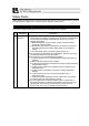
Safety Guide “Safety Guide” has been written to use the machine safely and so prevent personal injury or property damage beforehand. Make sure to read it before the operation of this product. Safety Precautions for Our Products The common safety precautions for the use of any of our robots in each operation. No.
No. 2 2 Operation Description Transportation 3 Storage and Preservation 4 Installation and Start Description Ɣ When carrying a heavy object, do the work with two or more persons or utilize equipment such as crane. Ɣ When the work is carried out with 2 or more persons, make it clear who is to be the leader and who to be the follower(s) and communicate well with each other to ensure the safety of the workers.
No. 4 Operation Description Installation and Start Description (2) Cable Wiring Ɣ Use our company’s genuine cables for connecting between the actuator and controller, and for the teaching tool. Ɣ Do not scratch on the cable. Do not bend it forcibly. Do not pull it. Do not coil it around. Do not insert it. Do not put any heavy thing on it. Failure to do so may cause a fire, electric shock or malfunction due to leakage or continuity error.
No. 4 5 4 Operation Description Installation and Start Teaching Description (4) Safety Measures Ɣ When the work is carried out with 2 or more persons, make it clear who is to be the leader and who to be the follower(s) and communicate well with each other to ensure the safety of the workers. Ɣ When the product is under operation or in the ready mode, take the safety measures (such as the installation of safety and protection fence) so that nobody can enter the area within the robot’s movable range.
No. 6 7 Operation Description Trial Operation Automatic Operation Description Ɣ When the work is carried out with 2 or more persons, make it clear who is to be the leader and who to be the follower(s) and communicate well with each other to ensure the safety of the workers. Ɣ After the teaching or programming operation, perform the check operation one step by one step and then shift to the automatic operation.
No. 8 9 6 Operation Description Maintenance and Inspection 10 Modification and Dismantle Disposal 11 Other Description Ɣ When the work is carried out with 2 or more persons, make it clear who is to be the leader and who to be the follower(s) and communicate well with each other to ensure the safety of the workers. Ɣ Perform the work out of the safety protection fence, if possible.
Alert Indication The safety precautions are divided into “Danger”, “Warning”, “Caution” and “Notice” according to the warning level, as follows, and described in the Instruction Manual for each model. Level Degree of Danger and Damage Symbol This indicates an imminently hazardous situation which, if the Danger product is not handled correctly, will result in death or serious injury.
Caution in Handling 1. Ensure use of the product in the specified conditions, environments and ranges. Operation out of the specified conditions could cause a drop in performance or malfunction of the product. 䎃 2. Do not conduct any treatment or operation that is not stated in this instruction manual.䎃 䎃 3. For the wiring of the controller and actuator, use the IAI product.䎃 䎃 4. Do not attempt to establish the settings for the speed and acceleration/deceleration above the allowable range.
11. This Actuator Requires a Home-Return Operation after Startup.䎃 For Slim Types (SA1L, SA2L and SA3L), the home position is one point in the center of the main body.(Can not be changed.) For Long Stroke Types (SA4L, SA5L, SA6L, SM4L, SM5L and SM6L), the home position is on the rear side in standard. For Single Slider Types (SA4L, SA5L and SA6L), home reversed type can also be selected.䎃 䎃 12. Handle the stainless steel sheet with special care.
International Standards Compliances This actuator complies with the following overseas standard. Refer to Overseas Standard Compliance Manual (ME0287) for more detailed information.
Names of the Parts In this manual, the right and left sides of the actuator are expressed in the way it is placed horizontally as shown in the figure below, and is looked at from the motor side.
12
1. Specifications Check Checking the Product 1. Specifications Check 1.1 The standard configuration of this product is comprised of the following parts. See the component list for the details of the enclosed components. If you find any broken or missing parts, contact your local IAI distributor. 1.1.1 No. 1 Components Name Main Body Model number Quantity Refer to “How to Read the Model Nameplate” and “How 1 to Read the Model Number.
1. Specifications Check 1.1.3 How to Read the Model Nameplate Model Serial Number 1.1.4 MODEL RCL-SA4L-I-2-N-40-A1-P SERIAL No.
1.2 Specification 1.2.1 Speed Single Slider Type Type SA1L SA2L SA3L Maximum speed [mm/s] 420 460 600 Ɣ Long Stroke Type Type Single Slider Type Double Slider Type Single Slider Type Double Slider Type Single Slider Type Double Slider Type 1.
1. Specifications Check 1.2.2 Acceleration and Transportable Weight available for Continuous Operation The acceleration is determined by the transported weight and the duty. From the table below, determine the acceleration from Continuous Operation (Duty 100%) when the duty is over 70% and up to 100%, and Duty 70% or less when it is 70% or below. Ɣ Slim Type Single Slider Type Transportable weight [kg] Max. Type acceleration Continuous operation Duty 70% or less [G] (Duty 100%) 0.1 0.5 0.5 0.3 0.5 0.
1.2.3 Rated Thrust and Transient Maximum Thrust Ɣ Slim Type Ɣ Long Stroke Type Type Single Slider Type Double Slider Type Single Slider Type Double Slider Type Single Slider Type Double Slider Type 1.2.4 SA4L SM4L SA5L SM5L SL6L SM6L Rated thrust [N] 2 4 8 Transient maximum thrust [N] 10 18 30 Rated thrust [N] Transient maximum thrust [N] 2.5 10 5 18 10 30 1. Specifications Check Single Slider Type Type SA1L SA2L SA3L Encoder Resolution 0.042mm 1.2.5 No.
Allowable Load Moment and Allowable Overhang Length for Actuator [1] Allowable Load Moment Ɣ Slim Type Single Slider Type Allowable load moment [N•m] Type Ma Mb Mc SA1L 0.13 0.12 0.21 SA2L 0.2 0.17 0.25 SA3L 1.22 1.08 0.34 Allowable overhang load length [L] Ma direction : 50mm or less Mb, Mc direction : 50mm or less Ma direction : 60mm or less Mb, Mc direction : 60mm or less Ma direction : 120mm or less Mb, Mc direction : 80mm or less Mb Mc L Ma L 1. Specifications Check 1.2.
Ɣ Long Stroke Type Type SA4L SM4L SA5L SM5L SA6L SM6L Allowable overhang load length [L] 0.2 0.17 0.25 Ma direction : 60mm or less Mb, Mc direction : 80mm or less 0.49 0.41 0.72 Ma direction : 60mm or less Mb, Mc direction : 100mm or less 0.87 0.75 1.
1. Specifications Check 1.3 Option 1.3.1 Reversed Home Type (Model No. : NM) The home position is located on the motor side in standard, however, if it is necessary to have it on the other side for such reasons as the layout of the system, the home position can be located on the other side by option.
1.4 Motor • Encoder Cables 1.4.1 Motor • Encoder Integrated Cables (For AMEC, ASEP) 1. Specifications Check CB-APSEP-MPAƑƑƑ Controller side Mechanical side Electric wire color Black White Brown Green Yellow Red Orange Gray White Yellow Red Green Black Brown Black Brown Green Red White Yellow shield Signal name U V W – – – BK+ BKA+ AB+ BZ+ ZLS+ LSGNDLS VPS VCC GND – FG Pin No. Pin No.
1.4.3 Motor • Encoder Integrated Cables (For ACON, ASEL) 1. Specifications Check CB-ACS-MPAƑƑƑ (Front View) (Front View) Mechanical side Electric wire color Red Yellow Black Yellow (Red㨯) Yellow (Blue㨯) Pink(Red㨯) Pink(Blue㨯) White(Red㨯) White(Blue㨯) Orange(Red㨯) Orange(Blue㨯) Gray(Red㨯) Gray(Blue㨯) Orange (Red㨯continuous) Orange (Blue㨯continuous) Gray (Red㨯continuous) Gray (Blue㨯continuous) shield 22 Signal name U V W – Controller side Pin No. Pin No.
2. Installation 2.1 Transportation (1) Handling the Packed Unit y Do not damage or drop. The package is not applied with any special treatment that enables it to resist an impact caused by a drop or crash. y An operator should never attempt to carry a heavy package on their own. Also, use an appropriate way for transportation. y Keep the unit in a horizontal orientation when placing it on the ground or transporting. Follow the instruction if there is any for the packaging condition.
[2] Handling in the Assembled Condition 2. Installation This is the case when the product is delivered from our factory under a condition that it is assembled with other actuators. The combined axes are delivered in a package that the frame is nailed on the lumber base. The sliders are fixed so they would not accidently move. The actuators are also fixed so the tip of it would not shake due to the external vibration. (1) How to Handle the Package y Do not hit or drop the package.
2.2 Installation and Storage • Preservation Environment [1] Installation Environment y Where the actuator receives radiant heat from strong heat sources such as heat treatment furnaces y Where the ambient temperature exceeds the range of 0 to 40qC y Where the temperature changes rapidly and condensation occurs y Where the relative humidity exceeds 85% RH y This actuator possesses the water durability of IP67 protection structure.
2.3 How to Install This chapter explains how to install the actuator on your mechanical system. 2. Installation 2.3.
[2] Long Stroke Type U : With condition in installation orientation(Note 1) u : Not possible Vertical Sideway Ceiling mount installation installation installation { u U 2. Installation { : Possible Horizontal installation SA4L, SA5L, SA6L SM4L, SM5L, SM6L { Installation Orientation Horizontal Vertical Sideway Ceiling mount Note 1 For horizontally oriented wall mount, set the slider side up as shown below.
2. Installation 2.3.2 Installing the Main Body x Make sure the platform to install the actuator possesses a structure with sufficient stiffness, so vibration would not be generated. x The surface where the actuator will be mounted should be a machined surface or that with an accuracy equivalent to it, and the flatness should be 0.05mm/m or below. x Have enough space for the maintenance work.
[2] Long Stroke Type Reamed hole for positioning Tapped hole for base attachment Slotted hole for positioning 2. Installation Base seating surface Tapped holes diameter Type Single Slider Type Double Slider Type Single Slider Type Double Slider Type Single Slider Type Double Slider Type SA4L SM4L SA5L SM5L SA6L SM6L Effective tapped depth M3 5mm M4 Recommended screw torque Seating surface : Seating surface : Copper Aluminum Reamed holes diameter 154N㨯cm (15.8kgf㨯cm) 83N㨯cm (8.
2.3.3 Attachment of Transported Objects [1] Slim Type SA1L, SA2L, SA3L 2. Installation Attach a transported object with utilizing the tapped holes on the slider surface. For the detailed dimensions, refer to the appearance drawing.
[2] Long Stroke Type SA4L, SA5L, SA6L SM4L, SM5L, SM6L Attach a transported object with utilizing the tapped holes on the slider surface. For the detailed dimensions, refer to the appearance drawing. 2.
3. Connecting with the Controller 3. Connecting with the Controller As the connection cable for the controller and the actuator, use the IAI dedicated controller and dedicated connection cable. This section, explains how to layout wires for single axis. x If the dedicated connection cable cannot be secured, reduce the load on the cable by allowing it to deflect only by the weight of the cable or wire it in a self–standing cable hose, etc., having a large radius.
[Connecting with the ACON and ASEL Controller] Dedicated Connection Cable (connects controller and RCL) r=84mm or more (Movable Use) r=42mm or more (Fixed Use) 33 3. Connecting with the Controller Dedicated Controller ACON ASEL Dedicated cables x Servo Motor Cable CB-ACS-MPAƑƑƑ ƑƑƑ shows the cable length. The max. length should be 10m.
Warning: For wiring, please follow the warnings stated below. When constructing a system as the machinery equipment, pay attention to the wiring and connection of each cable so they are conducted properly. Not following them may cause not only a malfunction such as cable breakage or connection failure, or an operation error, but also electric shock or electric leakage, or may even cause a fire. • Use dedicated cables of IAI indicated in this Instruction manual.
• Do not pull the cable with a strong force. 3. Connecting with the Controller • Pay attention not to concentrate the twisting force to one point on a cable. • Do not pinch, drop a heavy object onto or cut the cable. • When a cable is fastened to affix, make sure to have an appropriate force and do not tighten too much. Do not use spiral tube in any position where cables are bent frequently.
• PIO line, communication line, power and driving lines are to be put separately from each other and do not tie them together. Arrange so that such lines are independently routed in the duct. 3. Connecting with the Controller Power line Duct I/O lines (flat cable) Follow the instructions below when using a cable track. • If there is an indication to the cable for the space factor in a cable track, refer to the wiring instruction given by the supplier when storing the cable in the cable track.
4. Operational Conditions 4.1 Acceleration of the Setting 4.1.1 Slim Type SA1L, SA2L, SA3L SA2L Transportable Weight (horizontal) and Acceleration 0.6 1.2 0.5 1 0.4 Continuous Operation Available Duty 70% Control 0.3 0.2 0.1 0 Weight [kg] Weight [kg] SA1L Transportable Weight (horizontal) and Acceleration 0.8 Continuous Operation Available Duty 70% Control 0.6 0.4 0.2 0 0.5 1.5 1 Acceleration [G] 0 2 0 0.5 1.
4.1.2 Long Stroke Type SA4L, SA5L, SA6L SM4L, SM5L, SM6L The graph below shows the upper limit of transportable weight and acceleration available for continuous operation. SA5L, SM5L Transportable Weight (horizontal) and Acceleration 1.0 2.0 0.8 1.5 Weight [kg] Weight [kg] 4. Operational Conditions SA4L, SM4L Transportable Weight (horizontal) and Acceleration 0.6 0.4 0.2 0 1.0 0.5 0 0 0.5 1 Acceleration [G] 1.5 2 0 0.5 1 1.
4.2 4.2.1 Reference for Cycle Time Slim Type SA1L, SA2L, SA3L The graph below shows the cycle time in each acceleration pattern in maximum velocity. Take this as a reference for the operation time. 4. Operational Conditions Time [s] SA1L Cycle Time 0.60 0.55 0.50 0.45 0.40 0.35 0.30 0.25 0.20 0.15 0.10 0.1G 0.5kg 0.3G 0.5kg 0.5G 0.5kg 1G 0.25kg 1.5G 0.15kg 2G 0.1kg 10 0 20 40 30 Movement distance [mm] Time [s] SA2L Cycle Time 0.60 0.55 0.50 0.45 0.40 0.35 0.30 0.25 0.20 0.15 0.10 0.1G 1kg 0.
4.2.2 Long Stroke Type SA4L, SA5L, SA6L SM4L, SM5L, SM6L The cycle time for Long Stroke Type is referent values for when the gain adjustment is conducted considering the mounted load. SA4L Cycle Time 1.20 4. Operational Conditions 1.00 0.1G 0.8kg 0.3G 0.8kg Time [s] 0.80 0.5G 0.5kg 1G 0.25kg 0.60 0.40 1.5G 0.18kg 2G 0.14kg 0.20 0.00 0 30 60 90 120 150 180 Movement distance [mm] SA5L Cycle Time 1.20 1.00 0.1G 1.6kg 0.3G 1.6kg 0.5G 1.0kg 1G 0.5kg Time [s] 0.80 0.60 0.40 1.5G 0.
4.2.3 Gain Adjustment for Long Stroke Type (Servo Parameters) The initial setting parameter of the controller is set to be optimized when the load is small. For Long Stroke Types (SA4L, SA5L, SA6L, SM4L, SM5L and SM6L), it is necessary to change the gain setting in the parameters in case the load is big. Referring to the table below, have the parameter settings adjusted considering the mounted load weight. SA4L SM4L SA5L SM5L SA6L SM6L 4.
5. Maintenance Inspection 5.1 Inspection Items and Schedule 5. Maintenance Inspection Follow the maintenance inspection schedule below. It is assumed that the equipment is operating 8 hours per day. If the equipment is running continuously night and day or otherwise running at a high operating rate, inspect more often as needed. *1 5.
5.4 Ɣ Ɣ Ɣ Ɣ Ɣ Cleaning Clean exterior surfaces as necessary. Use a soft cloth to wipe away dirt and buildup. Do not blow too hard with compressed air as it may cause dust to get in through the gaps. Do not use oil–based solvents as they can harm lacquered and painted surfaces. To remove severe buildup, wipe gently with a soft cloth soaked in a neutral detergent or alcohol. 5.5 Grease Supply to the guide IAI uses the following grease in our plant. Kyodo Yushi Lithium Soap Based Grease Multemp PS No.
5.6 5. Maintenance Inspection 5.6.1 44 Replacement of the stainless steel sheet Slim Type SA1L, SA2L, SA3L 1) Remove the Phillips-head screws with using a precision Phillips screwdriver No. 0, and detach the oil stainless steel sheet. Prepare a piece of plain paper (with thickness of approximately 0.1mm) and cut it in a size with the width in the same as stainless steel sheet (SA1L: 8mm and SA2L/3L: 11mm) and length longer than the slider cover.
5.6.2 Long Stroke Type SA4L, SA5L, SA6L SM4L, SM5L, SM6L Remove the old stainless steel sheet. Prepare a piece of plain paper (with thickness of approximately 0.1mm) and cut it in a size with the width in the same as stainless steel sheet (SA4: 8mm and SA5/6: 11mm) and length longer than the slider cover. 2) Put the paper prepared in 1) through under the slider cover as shown in the picture. 3) Put a new stainless steel sheet through along the paper.
6. External Dimensions 6.1 Slim Type 6.1.1 Single Slider Type SA1L 30 4-M2 depth 3 Cable joint connector 12 19 12 (300) 178 2 15 3 14 Stroke=40 19 1 1 3 SE Home ME 30 26.5 9.6 ME Secure at least 100 Ma Moment datum point for offset 20 50 10 50 50 ME : Mechanical end SE : Stroke End 14 16 2 8-M2 depth 4 Weight : 0.28kg 6.1.2 SA2L 40 4-M2 depth 4 16 16 23 Cable joint connector (300) 214 19 3 2 Stroke=48 18 25 19 1 3 Home SE ME 11.3 ME 1 36 31.
6.1.3 SA3L 48 18 4-M3 depth 5 18 27 Cable joint connector (300) 278 2 23 30 1 SE Home ME 12.3 ME 23 Secure at least 100 6. External Dimensions 28 ME : Mechanical end SE : Stroke End 2 30 50 50 50 50 44 22 Ma Moment datum point for offset Stroke=64 1 5 36.5 42 5 23 10-M3 depth 4 Weight : 0.
6.2 6.2.1 Long Stroke Type Single Slider Type SA4L Cable joint connector 12 2-φ2H7 depth 2 Ma Moment datum point for offset 14 17 ± 0.02 (300) L (Stroke+78) 15 19.5 (1) 9 M.E. Stroke 30 28.5 (1) M.E. Home S.E. 25 (21.3) 13 (30) (0.6) 40 Secure at least 100 (0.6) A × 30P φ 3H7 depth 4 13.5 30 Oblong Hole, depth 4 (D) B-M3 depth 5 15 C M.E. : Mechanical end S.E. : Stroke End 14 4 3H7 +0.010 0 D 26 6.
6.2.2 SA5L 25 Cable joint connector Ma Moment datum point for offset 2-φ 2H7 depth 2.5 4-M2 depth 4 (through) 16 16 (Reamer pitch tolerance ±0.02) 7 16 22± 0.02 (300) L (Stroke+91) 19 21 (1) 13 40 30 (1) Home S.E. M.E. 30 (36) Secure at least 100 (0.6) 48 A ×36P 14 36 Oblong Hole, depth 4 (D) φ3H7 depth 4 18 C +0.010 0 4 B-M3 depth 5 16 3H7 D Detail D 1 Stroke L A B C Weight [kg] M.E. : Mechanical end S.E. : Stroke End 32 (0.6) 1 36 127 3 4 72 0.35 72 163 4 5 108 0.
6.2.3 SA6L 30 Cable joint connector 18.5 23 13 27 (1) M.E. Stroke L (Stroke+114) 18 25± 0.02 48 (1) Home S.E. (300) 39 M.E. (42) 58 5 36 Secure at least 100 (0.8) A × 48P 48 φ4H7 depth 4 B-M4 depth 5 24 C Oblong Hole, depth 4 (D) 9 +0.012 0 (0.8) 18.5 4H7 D Detail D 1 1 Stroke L A B C Weight [kg] 50 M.E. : Mechanical end S.E. : Stroke End 39.5 6. External Dimensions (30.3) 20.7 Ma Moment datum point for offset 2-φ3H7 depth 3.
6.3 Long Stroke Type 6.3.1 Double Slider Type SM4L Cable joint connector 20 5 2-φ2H7 depth 2 14 15 9 30 L (Stroke+147) Stroke 30 Stroke 30 (Minimum pitch of sliders) 28.5 (Minimum pitch of sliders) (1) M.E. Home Home (30) 40 (0.6) Secure at least 100 Secure at least 100 A × 30P Detail D 30 φ3H7 depth 4 13.5 B-M3 depth 5 15 14 C D 26 4 +0.010 0 Oblong Hole, depth 4 (D) 3H7 (0.6) (300) 6. External Dimensions (21.3) 30 12 17± 0.02 25 28.5 (1) M.E.
SM5L 25 7 2-φ2H7 depth 2.5 4-M2 depth 4 (through) 19 13 16 30 (1) M.E. 40 16 22± 0.02 L (Stroke+172) 30 (Minimum pitch of sliders) Stroke+2 40 Stroke+2 30 (Minimum pitch of sliders) 30 (1) Home Home (300) M.E. (0.6) (36) 48 30 (0.6) Secure at least 100 Secure at least 100 A × 36P 36 14 φ3H7 depth 4 B-M3 depth 5 18 D 32 4 +0.010 0 16 C 3H7 6. External Dimensions (25.3) 16 Ma Moment datum point for offset (300) Cable joint connector 16 (Reamer pitch tolerance ±0.02) 6.3.
SM6L 30 8 2-φ3H7 depth 3.5 4-M3 depth 5 (through) (300) 18 23 13 39 M.E. 40 Stroke+8 Stroke+8 40 48 Home Home (1) 39 M.E. 36 (30.3) (1) 48 (42) 58 (0.8) Secure at least 100 Secure at least 100 48 D Detail D 39.5 +0.012 0 5 1 φ4H7 Reamed, depth 4 B-M4 depth 5 24 18.5 C 9 1 1 M.E. : Mechanical end S.E. : Stroke End Stroke L A B C Weight [kg] 48 270 5 6 192 1.17 96 318 6 7 240 1.31 144 366 7 8 288 1.44 192 414 8 9 336 1.58 53 6. External Dimensions A × 48 4H7 (0.
7. How to use the home mark As necessary, affix these marks to the product to mark the home position of the actuator. Contents of sticker Home mark sticker × 1 sheet 7. How to use the home mark Home mark scale × 4 Home mark × 4 (Scale: 1 mm graduation mark, 10 mm width) • Peel off the marks from the base sheet. Note 1. Every mark has sticky back. 2. Remove smear and stain from the surface. 3. Avoid label or nameplate as a marking location.
8. Life The product life is assumed to be 5,000km (reference) under the condition that it runs with maximum load capacity and maximum acceleration/deceleration. 8.
9 Warranty 9.1 Warranty Period One of the following periods, whichever is shorter: • 18 months after shipment from our factory • 12 months after delivery to a specified location • 2,500 operational hours 9.2 Scope of the Warranty Our products are covered by warranty when all of the following conditions are met. Faulty products covered by warranty will be replaced or repaired free of charge: 9.
9.5 Conditions of Conformance with Applicable Standards/Regulations, Etc., and Applications (1) If our product is combined with another product or any system, device, etc., used by the customer, the customer must first check the applicable standards, regulations and/or rules. The customer is also responsible for confirming that such combination with our product conforms to the applicable standards, etc.
Change History Revision Date Revision Description First edition April 2009 Change History March 2013 58 Second edition • Long Stroke Type SA4L, SA5L, SA6L, SM4L, SM5L, SM6L added Third edition • Revised overall
Manual No.: ME3666-3A (March 2013) Head Office: 577-1 Obane Shimizu-KU Shizuoka City Shizuoka 424-0103, Japan TEL +81-54-364-5105 FAX +81-54-364-2589 website: www.iai-robot.co.jp/ Technical Support available in USA, Europe and China Head Office: 2690 W.