DeviceNet DeviceNet Gateway Unit RCM-GW-DV Operation Manual, Fifth Edition
DeviceNet Note Note on DeviceNet Products Take note that the IAI products listed below cannot be connected to Omron’s PLCs via DeviceNet.
CAUTION Note on Connecting PC or Teaching Pendant to Gateway Unit Grounded by Positive Terminal of 24-V Power Supply If the positive terminal of the gateway unit’s 24-V power supply is grounded, use a SIO converter, as shown below, to connect a teaching pendant or PC to the gateway unit. In this case, do not connect the FG on the SIO converter. Teaching pendant PC, etc. Make sure the FG on the PC is not connected to ground.
CAUTION If the positive terminal of the gateway unit’s 24-V power supply is grounded, a teaching pendant or PC cannot be connected directly to the gateway unit. If a teaching pendant or PC is connected directly to the gateway unit in this condition, the power circuit may be shorted and the PC or teaching pendant may be damaged. Gateway unit Cannot be connected directly. PC A teaching pendant cannot be used this way.
DeviceNet Gateway Table of Contents 1. Overview ................................................................................................................... 1 1.1 1.2 1.3 1.4 1.5 1.6 DeviceNet Gateway Unit ................................................................................................... 1 What Is DeviceNet?........................................................................................................... 2 Application Example of Gateway Unit ..............................
DeviceNet Gateway 7. Communication Signal Details ................................................................................ 80 7.1 7.2 7.3 7.4 Overview of Communication Signal Timings .................................................................. 80 Communication Signals and Operation Timings............................................................. 81 Basic Operation Timings .................................................................................................
DeviceNet Gateway 1. 1.1 Overview DeviceNet Gateway Unit The DeviceNet Gateway Unit (hereinafter referred to as “DeviceNet Gateway” or “Gateway Unit”) is used to connect a DeviceNet communication protocol network on which a host programmable controller (hereinafter “PLC”) operates, to a SIO communication sub-network (Modbus communication protocol) linking ROBO Cylinder controllers.
DeviceNet Gateway 1.2 What Is DeviceNet? (1) FA communication system In FA communication, each communication specification varies depending on the communicating equipment, type of information, and purpose of communication, among others. In general, however, the FA communication system is divided into the information level, controller level and field level, as shown below.
DeviceNet Gateway (5) DeviceNet DeviceNet is a device-level open network used widely for FA and other applications. Since the communication specifications are open, DeviceNet-compliant devices made by different manufacturers can communicate with one another without dedicated programs. Currently the DeviceNet standard is managed by a nonprofit organization called ODVA (Open DeviceNet Vendor Association, Inc.).
DeviceNet Gateway 1.4 Features and Key Functions 1.4.1 Features With the DeviceNet Gateway Unit, a desired operation mode can be selected from the position-number specification mode, direct numerical specification mode, and command specification mode. (1) Position-number specification mode In this mode, the actuator is operated by specifying position numbers. Up to 16 axes can be connected. The position data, speed, acceleration/deceleration, etc., must be entered beforehand in the position table.
5 Key function Commands Operation by position data specification Direct specification of speed and acceleration/deceleration Direct specification of positioning band Push-motion operation Operation by position number specification Enabling position table Maximum registrable positions Completed position number read Controller PIO pattern selection Zone (parameter) Position zone (P table) Various status signal read Speed change during movement Operation at separate acceleration and deceleration Current pos
DeviceNet Gateway The table below lists the number of positions available for each controller in each PIO pattern, and the corresponding maximum number of positions that can be registered for the Gateway Unit. Take note that the number of positions may be limited in some cases. PIO patterns (Parameter No.
DeviceNet Gateway 1.5 Description of Model Name Base model For DeviceNet Gateway Unit 1.6 Accessories [1] Power-supply input connector plug MC1•5/4-ST-3•5 [2] SIO communication connector plug MC1•5/6-ST-3•81 [3] DeviceNet communication connector plug SMSTB2•5/5-ST-5•08AU 1 pc (Phoenix Contact) 1 pc (Phoenix Contact) 1 pc (Phoenix Contact) None of the plugs come with a terminal resistor.
DeviceNet Gateway 2. 2.
DeviceNet Gateway External Dimensions (Installed dimension) 2.
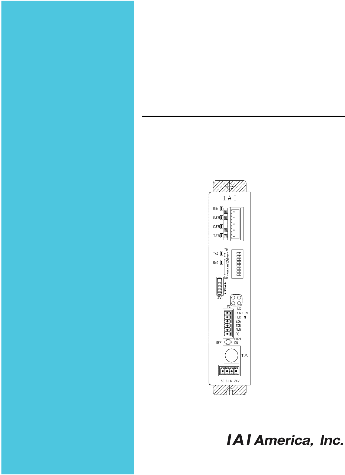
DeviceNet Gateway 2.3 Name and Function of Each Part [1] Gateway status indicator LEDs RUN: Normal G.ER: Error C.ER: DeviceNet error T.
DeviceNet Gateway [1] Gateway status indicator LEDs Each LED indicates the applicable conditions shown in the table below. If any of these LEDs indicates an abnormality, refer to 10.2, “Troubleshooting.” Indicated status RUN Steady green Unlit G.ER C.ER T.
DeviceNet Gateway [3] Mode setting switch This switch is used to set the operation mode of the DeviceNet Gateway. Operate the switch after turning off the DeviceNet Gateway power. If any number between Nos. 1 and 5 is selected, the position table settings in the controller will become invalid. SW1 turns ON when tilted to the right. : ON X: OFF SW1 No.
DeviceNet Gateway [7] Baud-rate setting switches Switches DR0 and DR1 are used to set a desired baud rate. Each switch turns ON when tilted to the left. {: ON X: OFF Baud rate DR1 125 K X 250 K X { 500 K [8] DR0 X { X Node-address setting switches Switches NA1 to NA32 are used to set a desired node address. Each switch turns ON when tilted to the left.
DeviceNet Gateway [9] DeviceNet communication status LEDs The two LEDs of MS and NS on the front face of the board indicate the node status and network status. (The remaining two LEDs are not used.) These LEDs illuminate in one of two colors (red or green), and each LED indicates a different monitored status, as shown in the table below. MS (Module Status) LED ..... This LED indicates the status of the node. NS (Network Status) LED ..... This LED indicates the status of the network.
DeviceNet Gateway [10] Port switch This switch is used to enable the teaching pendant/PC connector (TP) (PORT ON = Start communication). Set this switch to the OFF position when connecting/removing the communication cable connector for teaching pendant or PC software. To use the teaching pendant or PC software, plug in the connector first, and then set the switch to the ON position. (Also check the signal status of the port switching input [4].
DeviceNet Gateway 3. Installation and Noise Elimination Measures Exercise due caution regarding the installation environment. 3.1 Installation Environment. a. b. c. d. e. 3.2 The Gateway Unit is not dustproof or waterproof (oilproof). Accordingly, avoid using the Gateway Unit in a dusty place or place where the unit may come in contact with oil mist or splashed cutting fluid.
DeviceNet Gateway b. Notes on wiring method Separate the communication lines of the Gateway Unit and Profibus module from lines carrying large current such as power circuits. (Do not bundle them together or place them in the same cable duct.) c. Noise sources and elimination of noise There are many noise sources, but the ones you should pay most attention to when building your system are solenoid valves, magnet switches and relays. Noise from these sources can be eliminated using the following measures.
DeviceNet Gateway 3.4 Installation Examine appropriate settings for the control box size, installation position of the Gateway Unit and cooling method of the control box, so that the temperature around the Gateway Unit will remain at or below 40°C. Install the Gateway Unit vertically on a wall, as shown below, and provide a minimum clearance of 50 mm above and below the unit, with a minimum clearance of 100 mm provided on all sides for wiring access.
24-V power supply Teaching pendant 4-way junction DeviceNet Slave devices Terminal resistor Terminal block SIO communication network 4.1 Gateway Unit Communication power supply 4. T-junction Host system (PLC master) DeviceNet Gateway Wiring Overall Configuration Shown below is an example of the DeviceNet system configuration using the Gateway Unit.
DeviceNet Gateway DeviceNet network wiring is shown below. For details on DeviceNet, refer to the operation manual for the master (PLC). Shown below is an example of the DeviceNet network. DeviceNet unit (master) T-junction tap Node Main line Terminal resistors are installed. Terminal resistors are installed. Node Branch line Node Node Node Node Node Node Node 24-VDC communication power supply (1) A device with an address connected to the network is called “node.
DeviceNet Gateway About Grounding • • Do not ground the shield wires at multiple locations on the network. Always ground the shield wires at one location. Provide dedicated grounding separately from the inverters for drive systems, etc. (3) Nodes can be connected in one of two ways. Both methods can be employed together in a single network. [1] T-junction method --- A T-junction tap, etc., is used (Indicated by “T” in the network diagram on p.
DeviceNet Gateway 4.2 I/O Signals of Gateway Unit (1) Connection diagram Gateway Unit Black: DeviceNet cable Teaching pendant (V-) Light blue: (CAN_L) Clear: (Shield) White: (CAN_H) Red: (V+) Teaching pendant/ PC connector Emergency stop Port switch Teaching-pendant emergency stop signal output Allowable load voltage: 30 VDC Allowable load current: 1 A Gateway power supply 24 VDC ±10%, 300 mA max.
DeviceNet Gateway (2) Port control and emergency stop signal output The teaching pendant/PC connector port can be operated by external signals, other than by ON/OFF switching of the port switch on the Gateway Unit. While the port is ON, the Gateway Unit outputs contact signals of the emergency stop pushbutton switch on the teaching pendant. Therefore, you can design an emergency stop circuit or other protective circuit for the entire system by incorporating these signals.
SIO communication connector Power-supply input connector Symbol DeviceNet communication connector 24 (3) I/O signal specifications and wires PORT IN PORT N SDA Description Positive side of the 24VDC Gateway power supply Negative side of the 24VDC Gateway power supply Teaching-pendant emergency stop signal output External port switching input SIO communication line A SDB SIO communication line B GND Ground 24 V N S1 S2 FG Frame ground Black: (V-) Power supply - Light blue: (CAN_L) Clear: (S
DeviceNet Gateway 4.3 Design of SIO Communication Network (SIO Communication) 4.3.1 Wiring (1) Basics Item Number of connected units Communication cable length Communication cable Terminal resistor Description 16 axes max. (The specific number varies depending on the operation mode. Refer to 1.4, “Features of Gateway Unit.”) Total cable length: 100 m max. Double shielded twisted-pair cable (AWG22 --- Outer sheath diameter 1.35 to 1.
DeviceNet Gateway a. Detail connection diagram Details of SIO link connection are illustrated below. Controller link cables are available as options, but the customer must provide the communication trunk.
DeviceNet Gateway [Connection by Terminal Block or Joint] Gateway Unit Double shielded twisted-pair cable Recommended cable: HK-SB/20276 X L 2P X AWG22 by Taiyo Electric Wire & Cable Axis 1 Yellow Orange Blue If installing a terminal block is difficult or any other wiring limitation applies, connect the cable directly using a joint, instead of using a terminal block. Connect each wire using a round crimp terminal with a screw/nut, and then wrap an insulation tape around the connection point.
DeviceNet Gateway e-CON connector pin numbers Locking tab Always insert a terminal resistor (220 Ω, 1/4 W) at the end of the communication trunk (between pins 1 and 2 of the e-CON connector). Caution [1] When wiring to the e-CON connector, stripping the wires may cause the stripped wires to short inside the connector. [2] Wires that can be connected to the e-CON connector are those with an outer sheath diameter of 1.35 to 1.60. When pressure-welding a wire, use pliers, etc.
DeviceNet Gateway (3) Linking ERC2-SE controllers via SIO communication For details, refer to the operation manual for your ERC2-SE controller. Use 4-way junctions to link the controllers as shown below. The power-supply & I/O cable and network connection cable (including a 4-way junction or e-CON connectors) are standard accessories of each ERC2-SE controller.
DeviceNet Gateway (4) Linking ERC2-NP/PN controllers via SIO communication Use relay terminal blocks to link the controllers as shown below. Gateway Unit SGA Relay terminal block Orange (red 1) PIO power-supply & I/O cable CB-ERC-PWBIO Controller 1 SGB Orange (black 1) Controller 2 Paired shield cables (To be provided by the customer.
DeviceNet Gateway (5) Wiring the emergency stop (EMG) circuit When designing an emergency stop circuit that incorporates the emergency stop switch on the teaching pendant connected to the Gateway Unit, emergency stop signals output from the “S1” and “S2” terminals of the Gateway Unit can be used. This way, all connected ROBO Cylinder controllers can be stopped instantly in case of emergency by operating the emergency stop switch on the teaching pendant connected to the Gateway Unit. Caution 1.
DeviceNet Gateway [1] Example of cutting off drive signals Teaching pendant EMG pushbutton EMG reset switch Gateway Unit TP connector EMG pushbutton SIO connector PCON, ACON controller SIO communication Connection SIO detection connector signal (H) connection detection circuit Gateway power supply Port switch EMG signal detection (H) 24-VDC input power supply (2 A max.
DeviceNet Gateway [2] Example of cutting off motor drive power Teaching pendant EMG pushbutton EMG reset switch Gateway Unit TP connector EMG pushbutton SIO connector PCON, ACON controller SIO communication Connection SIO detection connector signal (H) connection detection circuit Gateway power supply Port switch EMG signal detection (H) 24-VDC input power supply (2 A max.
DeviceNet Gateway 4.3.2 Axis Number Setting The following explanation applies to PCON, ACON, SCON and ERC2 controllers. Set the axis number as a slave station number on the SIO communication network. The axis number of axis 1 is “0,” while that of axis 16 is “F.” Set an appropriate axis number using a hexadecimal value between 0 and F. Axis numbers can be set on the teaching pendant or in the PC software.
DeviceNet Gateway 4.4 How to Connect Teaching Tools When Grounding the Positive Terminal of the 24V Power Supply If the positive terminal of the gateway unit’s 24-V power supply is grounded (= +24-V side is grounded), use a SIO converter, as shown below, to connect a teaching pendant or PC to the gateway unit. In this case, do not connect the FG on the SIO converter. Teaching pendant PC, etc. Make sure the FG on the PC is not connected to ground.
DeviceNet Gateway 5. Overview of DeviceNet All data exchanged between the master station and the controller are tentatively stored in the internal memory of the Gateway Unit, and then transmitted cyclically. Accordingly, the PLC program recognizes these data as remote DeviceNet I/Os. Up to 16 ROBO Cylinder controllers can be connected to the Gateway Unit, with the connected controllers assigned an axis number of 0 to 15, respectively.
DeviceNet Gateway (1) Fixed assignment When a CJ-series master unit is used, one of three pairs of fixed assignment areas can be specified as assigned relay areas (using a specified soft switch). In other words, three master units can be installed in a single PLC, with each master unit assigned different areas. I/O memory address of CPU unit Output (OUT) area 1 Input (IN) area 1 Output (OUT) area 2 One of these area pairs is selected.
DeviceNet Gateway (2) Free assignment using a configurator By using a DeviceNet configurator, slaves can be assigned respectively to four blocks, including output area blocks 1 and 2 and input area blocks 1 and 2, in a desired node address order within each block. By using this free assignment function, up to 16 master units can be installed in a single PLC. Each block can occupy any position. For example, the blocks can be arranged in a sequence of IN block 1, OUT block 2, IN block 2 and OUT block 1.
DeviceNet Gateway 6. Address Configuration of Gateway Unit As explained in 1.4, “Features of Gateway Unit,” the connected controller(s) can be operated in three main modes. The slave address configuration is different in each of these modes. 6.1 Position-number Specification Mode In this mode, the actuator is operated by specifying position numbers in the position table. Up to 16 axes can be controlled. The position table must be set for each axis using the PC software or teaching pendant.
DeviceNet Gateway 6.1.1 Overall Address Configuration In the position number specification mode, the gateway control/status signal inputs and outputs use two words each. With each axis, each control signal consists of one word in each PLC I/O area, and 24 input words and 24 output words are occupied for the entire gateway unit. The values in parentheses indicate axis numbers. +00 +01 +02 +03 +04 +05 +06 +07 +08 +09 +10 +11 +12 +13 +14 +15 +16 +17 +18 +19 +20 +21 +22 +23 Cannot be used.
DeviceNet Gateway 6.1.2 Gateway Control/Status Signals As for the address configuration in each mode, the initial two channels provide signals used to control the Gateway Unit. Both input and output word registers consist of two words each. It is recommended that data in these word registers be transferred to, and used in, bit registers. Gateway control/status signals are used to control the ON/OFF status of SIO communication and monitor the SIO communication status and Gateway Unit status.
DeviceNet Gateway I/O Signal List Signal type PLC output Control signal 0 Bit Signal name 15 MON 14-8 --- 7 NPS4 6 NPS3 5 NPS2 4 NPS1 3 NPS0 2 PPS2 1 PPS1 0 PPS0 Description SIO link communication will start when this signal is turned ON, and stop when it is turned OFF. Do not turn the MON signal ON when CFG15 to 0 (linked axis connection) are all OFF. Also, do not turn all of CFG15 to 0 OFF when the MON signal is ON.
DeviceNet Gateway Signal type Bit Signal name Description Gateway Unit normal output 15 RUN Gateway Unit error detection output 14 G.ER SIO communication error detection output 13 T.ER 12 TPC 11 MOD4 10 MOD3 9 MOD2 8 MOD1 7 6 5 4 3 2 1 Major V.4 Major V.2 Major V.1 Minor V.16 Minor V.8 Minor V.4 Minor V.2 0 Minor V.
DeviceNet Gateway 6.1.3 Assignment for Each Axis With I/O signals for each axis, each PLC input or output area consists of one word (two bytes), respectively. Control and status signals consist of ON (1)/OFF (0) signal bits. Command position and completed position numbers are treated as one-byte (eight-bit) binary data. Specify command position numbers within the position number range set for each controller axis.
DeviceNet Gateway I/O Signal Details Signal type PLC input PLC output Command position number Control signal Zone signal output 2 Zone signal output 1 Completed position number (alarm output) Status signal Bit Six-bit data (b13-8) b7 b6 b5 b4 b3 b2 b1 b0 Signal name PC 32 to PC1 SON STP HOME CSTR RES b15 ZONE2 *2 b14 ZONE1 Six-bit data (b13-8) PM32 to PM1 b7 b6 b5 b4 b3 b2 b1 b0 EMGS PWR SV MOVE HEND PEND ALM Description Details Specify the command position number using a binary value.
DeviceNet Gateway [Alarm Description List] The list below shows the alarm descriptions to be output by PM8 to PM1 (as a binary code) while the corresponding alarms are present. For details of alarm descriptions, refer to the operation manual for the controller.
DeviceNet Gateway 6.2 Direct Numerical Specification Mode In the direct numerical specification mode, the actuator is operated by specifying the position data, speed, acceleration/deceleration, positioning band (push band), and current-limiting value for push-motion operation, directly in numerical values. There are five patterns, each accommodating a different number of connected axes. (The pattern is set using the mode setting switch SW1.) The current position data can be read at any time.
DeviceNet Gateway 6.2.1 Overall address configuration Each Gateway control/status signal input or output consists of two words. In the direct numerical specification mode, each axis control signal consists of the PLC output area (Gateway input area) containing six words and the PLC input area (Gateway output area) containing three words. The number of controlled axes is set using the mode setting switch (SW1), and the data areas will vary depending on the settings of this switch.
DeviceNet Gateway The overall address configuration is shown below. “CH” indicates the head address of assigned areas in the DeviceNet master. The values in parentheses indicate axis numbers.
DeviceNet Gateway 6.2.2 Gateway Control/Status Signals As for the address configuration in each mode, the initial two channels provide signals used to control the Gateway Unit. Both input and output word registers consist of two words each. It is recommended that data in these word registers be transferred to, and used in, bit registers. Gateway control/status signals are used to control the ON/OFF status of SIO communication and monitor the SIO communication status and Gateway Unit status.
DeviceNet Gateway I/O Signal List Signal type PLC output Control signal 0 Bit Signal name 15 MON 14-8 --- 7 NPS4 6 NPS3 5 NPS2 4 NPS1 3 NPS0 2 PPS2 1 PPS1 0 PPS0 Description SIO link communication will start when this signal is turned ON, and stop when it is turned OFF. Do not turn the MON signal ON when CFG15 to 0 (linked axis connection) are all OFF. Also, do not turn all of CFG15 to 0 OFF when the MON signal is ON.
DeviceNet Gateway Signal type Bit Signal name Description Gateway Unit normal output 15 RUN Gateway Unit error detection output 14 G.ER SIO communication error detection output 13 T.ER 12 TPC 11 MOD4 10 MOD3 9 MOD2 8 MOD1 7 6 5 4 3 2 1 Major V.4 Major V.2 Major V.1 Minor V.16 Minor V.8 Minor V.4 Minor V.2 0 Minor V.
DeviceNet Gateway 6.2.3 Assignment for each axis Control and status signals are set using ON (1)/OFF (0) signal bits, while current-limiting value for push-mode operation and acceleration/deceleration are set using one-byte (eight-bit) hexadecimal data. Speed, target position data, positioning band and current position data are one-and-a-half-word (24-bit) hexadecimal data. It is recommended that control and status signals be transferred to, and used in, bit registers.
DeviceNet Gateway PLC input = Axis status signal 1 word = 16 bits n (axis number): 0 to 15 Status signal (Sign) Current position data (signed integer) Cannot be used. Current position data (sign: 0 = Positive value, 1 = Negative value) Caution 1. Signed 24-bit hexadecimal data output or input from/to the PLC is treated as a negative value when the most significant bit is “1.” Take note that all these data are treated as normal numerical data within the PLC.
DeviceNet Gateway I/O Signal Details Signal type PLC output Target position data Currentlimiting value for push motion Speed Acceleration/ deceleration Bit 24-bit data 8-bit data 24-bit data 8-bit data Signal name --- --- --- --- Description Set a signed 24-bit integer (unit: 0.01 mm) based on hexadecimal notation Example) To specify +25.4 mm, set “0009ECH” (“2540” in decimal notation). (Notes) The maximum settable value is +9999.99 mm = 999999 (decimal value) = 0F423FH (hexadecimal value).
DeviceNet Gateway Signal type Signal name 24-bit data --- b15 --- b14 DIR b13 b12 b11 b10 b9 b8 b15-8 b7 b6 b5 b4 b3 b2 b1 b0 PUSH SON STP HOME CSTR RES --EMGS PSFL PWR SV MOVE HEND PEND ALM Current position data 24-bit data --- --- b15-8 --- PLC output Positioning band Bit Control signal PLC input Status signal Description Set a 24-bit integer (unit: 0.01 mm) based on hexadecimal notation Example) To specify +25.4 mm, set “0009ECH” (“2540” in decimal notation).
DeviceNet Gateway 6.3 Command Specification Mode In this mode, two patterns can be combined, including the pattern in which the actuator is operated by specifying the target position data in numerical values and specifying all other positioning data using position numbers (simple direct operation), and the pattern in which the actuator is operated by specifying position numbers only (positioner operation).
DeviceNet Gateway With each function, the top row indicates positioner operation, while the bottom row indicates simple direct operation.
DeviceNet Gateway 6.3.1 Overall address configuration Each Gateway control signal input or output consists of two words. Only in this mode, PPS0 to PPS2 and NPS0 to NPS4 of control word 0 are used to set the pattern and number of position-number specification axes. This is followed by the command I/O areas each consisting of seven words, and the Gateway control signal and command I/O areas each consisting of nine words. These areas are fixed.
DeviceNet Gateway Example of Address Configuration Output from PLC ⇒ Gateway Unit ⇒ Input to each axis b15 Upper byte b8 b7 Lower byte b0 Gateway control signal 0 Gateway control area Gateway control signal 1 Command I/O area b7 Lower byte b0 Gateway status signal 0 Request command Response command Data 0 Data 0 Data 1 Data 1 Data 2 Data 2 Data 3 Data 3 Data 4 Data 4 Fixed areas Data 5 Positioner operation axis (0) control signal Positioner operation axis (0) status signal Positioner o
DeviceNet Gateway 6.3.2 Gateway Control/Status Signals The first two channels of signals are used to control the gateway unit, and consist of two input wordresistor words and two output word-resistor words. It is recommended that data in these word registers be transferred to, and used in, bit registers. Gateway control/status signals are used to control the ON/OFF status of SIO communication and monitor the SIO communication status and Gateway Unit status.
DeviceNet Gateway I/O Signal List Signal type PLC output Control signal 0 Bit Signal name 15 MON 14-8 --- 7 NPS4 6 NPS3 5 NPS2 4 NPS1 3 NPS0 2 PPS2 1 PPS1 0 PPS0 Description SIO link communication will start when this signal is turned ON, and stop when it is turned OFF. Do not turn the MON signal ON when CFG15 to 0 (linked axis connection) are all OFF. Also, do not turn all of CFG15 to 0 OFF when the MON signal is ON.
DeviceNet Gateway Signal type Bit Signal name Description Gateway Unit normal output 15 RUN Gateway Unit error detection output 14 G.ER SIO communication error detection output 13 T.ER 12 TPC 11 MOD4 10 MOD3 9 MOD2 8 MOD1 7 6 5 4 3 2 1 Major V.4 Major V.2 Major V.1 Minor V.16 Minor V.8 Minor V.4 Minor V.2 0 Minor V.
DeviceNet Gateway 6.3.3 Assignment for each axis The I/O signals are associated with different area sizes and contents between positioner operation axes and simple direct operation axes. (1) Control/status signals of a positioner operation axis Each axis is assigned one word of PLC output (control signal) and one word of PLC input (status signal), as shown below. One of six patterns is used according to the PIO pattern set by the Gateway control signal PPS.
DeviceNet Gateway Pattern 0 Status signal Completed position number Status signal Completed position number Pattern 1 PLC input Pattern 2 Status signal Completed position number Status signal Completed position number Pattern 3 Pattern 4 Status signal Completed position number 65
DeviceNet Gateway I/O Signal Details Signal type b12 b11 b9 b9 b8 b7 b6 b8-b0 Signal name SON RES CSTR PWRT STP HOME BKRL JOGJOG+ JISL MOD PC*** b6-b0 ST0-ST6 b15 b14 b13 b12 b11 b11 BALM ALM EMGS SV PEND WEND 0 to 4 0 to 4 0 to 4 0 to 4 0, 2 to 4 1 b10 b9 b8 b7 b7 b6 b8 to b0 HEND RMDS PZONE ZONE1 MODS MOVE PM*** 0 to 4 0 to 4 0 to 2, 4 0, 4 1 0, 1 0 to 3 b6 to b0 PE0 to PE6 4 Bit PLC output b15 b14 b13 Control signal PLC input Command position number Status signal Completed position n
DeviceNet Gateway (2) Control/status signals of a simple direct operation axis Each axis is assigned four words of PLC outputs (control signals) and three words of PLC inputs (status signals), as shown below. The target position data and current position data are indicated by signed 32-bit hexadecimal integers that are multiples of 0.01 mm.
DeviceNet Gateway I/O Signal Details PLC output Signal type Signal name --- Target position data 32-bit data Movement data position number Control signal 16-bit data PC*** b15 b14-b13 b12 b11 b10 b9 b8 b7-b0 32-bit data BKRL --SON STP HOME CSTR RES ----- b15-b9 b8 --PMSS b7 b6 b5 b4 b3 b2 b1 b0 EMGS PSEL PWR SV MOVE HEND PEND ALM Current position data Status signal PLC input Bit Description Details Set a signed 32-bit integer (unit: 0.01 mm) based 7.
DeviceNet Gateway Caution For movement data that must be specified directly from the PLC using numerical values, the settings of corresponding “default parameter values” are not applied. This means that if any of these data is not specified numerically, the actuator will not operate or an alarm will generate. The table below summarizes how to specify movement data in each operation mode.
DeviceNet Gateway 6.3.4 Command Areas Command areas are available in the command specification mode, and the various commands explained below can be used to read/write the position table, among others. (1) Address configuration The request command area and response command area consist of seven words each (CH+2 to CH+8).
DeviceNet Gateway (2) Command list The available commands and corresponding command codes are listed below.
DeviceNet Gateway (3) Each command and data format [1] “Position table data write” command Command name Write a target position Write a positioning band Write a speed Write an individual zone boundary + Write an individual zone boundary – Write an acceleration CH+ +2 3 4 5 6 7 8 +2 3 4 5 6 7 8 +2 3 4 5 6 7 8 +2 3 4 5 6 7 8 +2 3 4 5 6 7 8 +2 3 4 5 6 7 8 PLC output (request) 1000H Position number Position data *1 PLC input (response) Same as the requested value, if the command was successful.
DeviceNet Gateway Command name Write a deceleration Write a currentlimiting value for push-motion operation *5 Write a load current threshold CH+ +2 3 4 5 6 7 8 +2 3 4 5 6 7 8 +2 3 4 5 6 7 8 *1) *2) *3) *4) *5) PLC output (request) 1006H Position number Deceleration data *4 0 Axis number 0 to FH *2 (RSV) (RSV) 1007H Position number 0000 ~ 00FFH (00FH: Maximum current) 0 Axis number 0 to FH *2 (RSV) (RSV) 1008H Position number 0000 ~ 00FFH (00FH: Maximum current) 0 Axis number 0 to FH *2 (RSV) (RSV) P
DeviceNet Gateway [2] “Position table data read” command Command name Read a target position Read a positioning band Read a speed CH+ +2 3 4 5 6 7 8 +2 3 4 5 6 7 8 +2 3 Read an individual zone boundary + Read an individual zone boundary – Read an acceleration 4 5 6 7 8 +2 3 4 5 6 7 8 +2 3 4 5 6 7 8 +2 3 4 5 6 7 8 PLC output (request) 1040H Position number 0 0 Axis number 0 to FH *1 (RSV) (RSV) 1041H Position number 0 0 Axis number 0 to FH *1 (RSV) (RSV) 1042H Position number 0 0 Axis number 0 to F
DeviceNet Gateway Command name Read a deceleration Read a currentlimiting value for push-motion operation *5 Read a load current threshold CH+ +2 3 4 5 6 7 8 +2 3 4 5 6 7 8 +2 3 4 5 6 7 8 *1) *2) *3) *4) *5) PLC output (request) 1046H Position number 0 0 Axis number 0 to FH *1 (RSV) (RSV) 1047H Position number 0 0 Axis number 0 to FH *1 (RSV) (RSV) 1048H Position number 0 0 Axis number 0 to FH *1 (RSV) (RSV) PLC input (response) Same as the requested value, if the command was successful.
DeviceNet Gateway [3] “Position table data write (ROM)” command Command name Position table data write (ROM) coil write Position table data write (ROM) completion coil write CH+ +2 3 4 5 6 7 8 +2 3 4 PLC output (request) 0DA0H 0 0 0 Axis number 0 to FH (RSV) (RSV) 02E0H 0 0 0 5 6 7 8 [4] Axis number 0 to FH (RSV) (RSV) PLC input (response) Same as the requested value, if the command was successful. Same as the requested value, if the command was successful.
DeviceNet Gateway [5] “Current value monitor” command Command name Current position of a specified axis CH+ +2 3 4 5 6 7 8 PLC output (request) 0440H 0 0 0 PLC input (response) Same as the requested value, if the command was successful.
DeviceNet Gateway [6] “Group-specified broadcast” command The axes specified by a group number are started simultaneously toward the position specified by a POS number. This command causes the Gateway to communicate with each ROBO Cylinder controller in the broadcast mode, and accordingly the ROBO Cylinder controller does not return any response.
DeviceNet Gateway (4) Error response If a command error occurs, the most significant bit (b15) of the response command will turn ON and a corresponding error code, as shown below, will be set in response data 1. If link is not yet established at all, nothing will be shown in the response command.
DeviceNet Gateway 7. 7.1 Communication Signal Details Overview of Communication Signal Timings When a given control signal is turned ON to operate the ROBO Cylinder controller using the sequence program in the PLC, the maximum response time before a response (status) signal will be received is expressed by the formula below: Maximum response time (msec) = Yt + Xt + 2 x Mt + Command processing time (operation time, etc.
DeviceNet Gateway 7.2 Communication Signals and Operation Timings (1) Controller ready (PWR) PLC input signal This signal turns “1” (ON) when the controller becomes ready to perform control following the power on. Function This signal turns “1” (ON) when the controller has been successfully initialized following the power on and becomes ready to perform control, regardless of the alarm condition, servo status, etc.
DeviceNet Gateway (5) Pause (STP) PLC output signal Turning this signal “1” (ON) causes the axis movement to pause (= the axis will decelerate to a stop). Turning it “0” (OFF) resumes the axis movement. The relationship between the STP signal and MOVE (moving) signal is shown below.
DeviceNet Gateway (8) Home return command (HOME) PLC output signal Home return complete (HEND) PLC input signal Home return operation is started at the leading edge of the HOME signal from “0” (OFF) to “1” (ON). The HEND (home return complete) signal turns “1” (ON) when the home return is completed. Turn the HOME signal “0” (OFF) after the HEND signal has turned “1” (ON). Once turned “1” (ON), the HEND signal will not turn “0” (OFF) until the power is turned off or the HOME signal is input again.
DeviceNet Gateway (9) Positioning start (CSTR) PLC output signal Upon detection of the leading edge of this signal from “0” (OFF) to “1” (ON), the target position number corresponding to the binary code consisting of PC1 to PC322768 (The specific signals used vary depending on the operation mode) will be read and the actuator will position itself to the target position specified by the applicable position data.
DeviceNet Gateway (11) Command position number (PC1 to PC512) PLC output signal The command position number is read as a binary code.
DeviceNet Gateway (14) Jog + command/jog- command (JOG+/JOG-) PLC output signal These signals are used to operate the actuator in PIO pattern 1 (teaching mode) as a positioner operation axis in the command specification mode. They are used as starting commands for jogging and inching. When the + command is issued, the actuator moves in the direction opposite home. When the – command is issued, the actuator moves in the direction of home.
DeviceNet Gateway (15) Jog/inching switching (JISL) PLC output signal This signal is used to switch between jogging and inching. JISL = “0” (OFF) : Jogging JISL = “1” (ON) : Inching If the JISL signal switches to “1” (ON) while the actuator is jogging, the actuator will decelerate to a stop and then the inching function will be performed. If the JISL signal switches to “0” (OFF) while the actuator is inching, the actuator will complete the inching and then the jogging function will be performed.
DeviceNet Gateway (17) Position data read command (PWRT) PLC output signal Position data read complete (WEND) PLC input signal These signals are used when the actuator is operated in PIO pattern 1 (teaching mode) as a positioner operation axis in the command specification mode. The PWRT signal is effective when the MODS signal is “1” (ON).
DeviceNet Gateway 7.3 Basic Operation Timings (1) Ready Start the actuator by following the procedure below after confirming that the slider or rod is not colliding with a mechanical end and the load is not contacting any surrounding equipment: [1] Cancel the emergency stop or enable energization of the motor drive power. [2] Supply the 24-VDC controller power: 24-V and 0-V terminals on the power-supply terminal block [3] Set the minimum required parameters.
DeviceNet Gateway Warning With the ACON, the excited magnetic phase is detected when the servo turns ON for the first time after the power on. Because of this operation, the actuator normally moves by approx. 0.5 to 2 mm, although the specific value varies depending on the ball screw lead. (On rare occasions, the actuator may move by up to one half the ball screw lead depending on the position where the power is turned on.
DeviceNet Gateway (2) Home return operation Since the controller unit adopts an incremental position detector (encoder), the mechanical coordinate values will be lost once the power is cut off. For this reason, home return must be performed after the power is turned on in order to establish the mechanical coordinate values. To perform home return operation, input the home return command (HOME) signal.
DeviceNet Gateway (3) Operation by position number specification The following explains positioner operation in the position number specification mode or command specification mode. Operation Enter position data in the controller’s position table beforehand, and specify each desired position number using the applicable link resister in the PLC.
DeviceNet Gateway [1] Command position number [2] Start command [3] [4] Position complete [6] Completed position number [5] Moving *1 *2 T1: Set T1 as 0 ms or greater by considering the scan time of the host controller.
DeviceNet Gateway (4) Operation in the direct numerical specification mode A function is provided to operate the actuator in the push-motion operation mode by writing the position data, acceleration/deceleration data, speed data, current-limiting value and positioning band directly to the link registers in the PLC, without using the position table in the controller. In the case of push-motion operation, all of the above data are set.
DeviceNet Gateway [1] Position data setting [2] Speed and acceleration/deceleration setting [3] Set value of positioning band data [4] Set value of pushcurrent limiting data [5] Push mode [6] Push direction [7] Start command Position complete/ work missed [13] [9] [8] [11] Current position [12] [10] Moving *1 T1: Set T1 as 0 ms or greater by considering the scan time of the host controller.
DeviceNet Gateway The target position data, acceleration/deceleration data, speed data, positioning band data and pushcurrent limiting data can be changed while the actuator is moving. After the applicable data has been changed, turn CSTR “1” (ON) for at least tdpf. Also wait for 1 Mt or more after CSTR is turned “0” (OFF) until CSTR is turned “1” (ON) again. An example of changing the speed and acceleration/deceleration data is shown below.
DeviceNet Gateway (5) Simple direct operation (Command specification mode) The actuator is operated by writing the target position data in the PLC’s link register and specifying other data such as the speed, acceleration/deceleration, positioning band and push-current limiting value in the position table. Preparation Set all position data other than the target position (= speed, acceleration/deceleration, positioning band and push-current limiting value, etc.) in the position table.
DeviceNet Gateway [1] Position data setting [2] Command position [3] Start command [4] [5] Position complete [7] Current position [6] Moving *1 T1: Set T1 as 0 ms or greater by considering the scan time of the host controller.
DeviceNet Gateway 7.4 Command Transmission Commands can be used in the command specification mode. A timing chart of command transmission is given below. Every time control/status data is exchanged for any of the connected axes in normal operations, the Gateway Unit analyzes each request command and responds to the command. The PLC and Gateway perform the following steps: [1] After confirming zeros in a response command, the PLC application sets the next request command and data required.
DeviceNet Gateway 100
DeviceNet Gateway 8. 8.1 Network System Building Procedure Procedure The procedure to start up a DeviceNet network using the gateway unit is shown below. (1) Installation Install the DeviceNet gateway unit, axis controller and other necessary units in the control panel. ↓ (2) Wiring Wire the gateway unit’s 24-V power supply and field network, and also wire for SIO communication, etc. (Refer to 4.) ↓ (3) Set the address of each axis controller (Refer to 4.3.2 and 8.2.
DeviceNet Gateway 8.2 Settings for Controller Communication For the controller to be able to communicate with the Gateway, the settings specified below must be performed. (1) Setting the axis number Set a unique axis number in a range of 0 to 15. Take note that the range of settable axis numbers varies depending on the operation mode of the Gateway Unit. The steps to set an axis number using the PC (software) are explained below.
DeviceNet Gateway (2) Setting the baud rate for SIO communication Set the applicable parameter using the PC software or teaching pendant in the same manner as in (1). [1] Set parameter No. 16, “SIO baud rate” to “230400” (230.4 kbps). SIO communication cannot be performed at any other baud rate but 230.4 kbps. [2] Set parameter No. 17, “Slave transmitter activation minimum delay” to “5” or less. To turn the communication cycle at the maximum speed, set “0.
DeviceNet Gateway 8.3 Setting the Gateway Unit and PLC Master For the Gateway Unit to be able to communicate with the master station. This setting must be the same between the master station and gateway unit. : ON X: OFF Gateway Unit setting Item PLC master setting Baud-rate setting Baud-rate setting switches switches Gateway node Address setting switch addresses Mode setting switch Occupied area SW1 settings No.
DeviceNet Gateway 8.4 Assigning the Master PLC Address by Free Assignment Slave address assignment can be performed automatically using a DeviceNet configurator. *1 Omron’s configurator comes preinstalled with an EDS file for Omron DeviceNet products. However, this file must be installed separately in the Gateway Unit to support IAI slave devices. Download the EDS file from IAI’s website. Website: http://www.iai-robot.co.jp File name: rcm-gw-dv.
DeviceNet Gateway 8.4.2 Creation of Network Configuration (1) Installing a EDS file [1] [2] [3] In the hardware list shown on the left side of the initial window, select “Communications Adapter” under “Device Type.” Click EDS File (S), and then select Install (I). Specify the location where the EDS file is stored, and install the file. When the registration is complete, a new level for HMS Fieldbus System AB is created below Vendor.
DeviceNet Gateway (2) Registering the master station Register the master station (CJ1W-DRM21) to the network. [1] Manual operation • Drag the master unit from the hardware list and drop it onto the network configuration pane. • In the above window, bring the arrow over the master (to select the node), and then click the right mouse button. Next, double-click Change Node Address (A).
DeviceNet Gateway • [2] Next, set the node address to 63 (a desired value between 0 and 63 can be selected). Automatic recognition • Click Network Upload. • The master station (CJ1W-DRM21) is automatically recognized and registered in the network configuration pane on the right side of the window.
DeviceNet Gateway (3) Registering the slave In the hardware list, select the EDS file list you have registered in (1), and then drag and drop the file to add it the network configuration pane. The slave is automatically assigned a node address in the order in which it is registered in the network configuration pane. 8.4.3 Creating a Scan List A scan list is where the slaves that communicate with the master via remote I/O communication over the DeviceNet network are registered.
DeviceNet Gateway [2] [3] [4] When the AnyBus-S DeviceNet Properties window appears, click the “I/O Information” tab, and then click Edit. When the I/O size change window appears, go to the Poll area and set IN/OUT sizes in the respective fields. In the screen shown below, the Gateway Unit is used in the position-number specification mode. (OUT = 48 bytes, IN = 48 bytes) After both sizes have been set, click OK to display the AnyBus-S Properties window.
DeviceNet Gateway (2) Registering the slave station (Gateway Unit) to the master [1] In the network configuration pane, drag the slave station and drop it over the master to register the slave to the master. [2] In the network configuration pane, double-click the master station to open the device parameters edit window and confirm that the items shown in the list of registered devices correspond to the settings you have entered in step (1) of 8.4.3.
DeviceNet Gateway [3] Still in the device parameters edit window, go to the “Master I/O Assignment (OUT)” tab and “Master I/O Assignment (IN)” tab to check the results of automatic assignment.
DeviceNet Gateway [4] Once the slave station has been registered in the master station, a return-arrow icon and a master node address preceded by # are displayed at the bottom right of the slave station icon.
DeviceNet Gateway 8.4.4 Online Connection (1) Click Network (N) and then select Connect to bring the system online. (You can also click the Connect icon in the toolbar.) (2) When the interface settings window appears, set each item as shown in the sample screen below, and then click OK.
DeviceNet Gateway (3) When the system has been successfully brought online, the indicator in the status bar found in the bottom right-hand corner of the screen changes to blue and the text changes from “Off-line” to “Online.” 8.4.5 Downloading the Master Scan List Download to the network master the scan list, settings and other information that have been creased and updated to this point. Take note that the PLC must be in the “program mode” to be able to download the scan list.
DeviceNet Gateway (2) When the following message dialog box appears asking whether you really want to write the device parameters, click Yes. (3) When all device parameters have been written, click Yes.
DeviceNet Gateway 8.5 Assigning the Master PLC Address by Fixed Assignment Area 1 (3200CH to 3263CH/3300CH to 3363CH) is assigned. The procedure to assign this area using CX-Programmer (version 6.0 or later) is explained below. Take note that an I/O table for the PLC system is assumed to have been created in advance. For details, refer to the operation manual for your PLC. (1) Bring CX-Programmer online, and then change the mode to “Program.
DeviceNet Gateway 9. Example of DeviceNet Operation An example of operating the ERC2-SE and PCON-SE via DeviceNet using Omron’s PLC is explained. Configuration Overview Node address 63 (Omron) Power supply 9.
DeviceNet Gateway 9.2 Actuator Operation Pattern Both linked axes 0 and 1 are operated in the position-number specification mode. The operation pattern is specified below. Specifically, position No. 0 is specified to cause the actuator to move to position No. 0 after completion of home return. The actuator pauses for 1 second in this position, after which position No. 1 is specified to cause the actuator to move to position No. 1.
DeviceNet Gateway 9.4 Setting Up the Gateway Unit (1) Setting the Gateway Unit mode Since the actuators are operated in the position-number specification mode, set each position of the mode setting switch (SW1) as follows: 1: OFF 2: ON 3: OFF 4: OFF (2) Setting the node address and baud rate for the Gateway Unit Node address = 0 Baud rate = 500 kbps (example) To effect the above settings, set the DIP switches as follows: DR1: ON DR2: OFF NA1, 2, 4, 8, 16, 32: All OFF 9.
DeviceNet Gateway Regardless of whether free assignment or fixed assignment is used, Gateway Unit addresses will be assigned as follows. Inputs and outputs will each occupy 24 channels. (Axes 0 and 1 are physically used.
DeviceNet Gateway 9.7 Ladder Sequence Flowchart An operation flowchart of Axes 0 and 2, which are both DeviceNet slave axes, is shown below. Gateway Unit normal? b15 = 1 and b14 = b13 = 0, for 3300CH Specify the SIO-linked axes. Set b0 and b1 of 3201CH to “1.” Start SIO link. Check the axis (0) (1) power. [2] Turn on the axis (0) (1) servo. Issue a P. No. 0 command to axis (0) (1). Set b15 of 3200CH to “1.” b5 of 3302CH and b5 of 3303CH are “1.” Set b4 of 3202CH and b4 of 3203CH to “1.
DeviceNet Gateway [1] Issue a P. No. 1 command to axis (0) (1). Set CSTR to “1.” Set CSTR to “0.” Positioning to P. No.
DeviceNet Gateway 10. Troubleshooting 10.1 Actions to Be Taken upon Problems If you encountered a problem, follow the steps below to take appropriate actions in order to restore the system quickly and prevent the same problem from occurring again: a. Check the statuses of various LED indicators on the Gateway Unit. [1] Gateway Unit status indicator LEDs (RUN, G.ER, C.ER, T.ER) [2] SIO communication status LEDs (TxD, RxD) [3] DeviceNet communication status LEDs (MS, NS) b.
DeviceNet Gateway 10.2 Failure Diagnosis Failure conditions are classified into the following three types: a. b. c. 10.2.1 Gateway Unit (CPU or power supply) error DeviceNet communication error ROBO Cylinder controller error Gateway Unit (CPU or Power Supply) Error If the Gateway status indicator LED RUN (green) turns off G.ER (red) turns on while the specified power is supplied, the Gateway Unit is experiencing a control error. Check the power-supply voltage of the Gateway Unit.
DeviceNet Gateway [2] [3] [4] [5] Check if CFG15 to 0 (linked axis selection) are set correctly. Check if the power and 0-V lines between the controller and Gateway Unit are common. Particularly when multiple units are linked, make sure all 0-V lines are common. Check if the terminal resistors are connected correctly and if their resistances are appropriate. Check if a power line or any other noise source is wired near the controller, Gateway Unit or SIO communication line.
DeviceNet Gateway 10.2.4 Troubleshooting for DeviceNet Communication If you encountered a problem with DeviceNet, check the operating condition and remove the cause by referring to the table below. The monitor LEDs illuminate in two different colors (red/green). The statues of these indicators can be used to check the DeviceNet status. If an error occurs, the MS or NS LED will illuminate or blink in red.
Catalog No.: ME0168-5A (2009) Head Office: 2690 W. 237th Street, Torrance, CA 90505 TEL (310) 891-6015 FAX (310) 891-0815 Chicago Office: 1261 Hamilton Parkway, Itasca, IL 60143 TEL (630) 467-9900 FAX (630) 467-9912 Atlanta Office: 1220-E Kennestone Circle, Marrietta, GA 30066 TEL (678) 354-9470 FAX (678) 354-9471 website: www.intelligentactuator.