
Manual
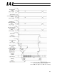


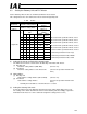
Table Of Contents
- 1. Overview
- 2. Specifications and Name of Each Part
- 2.1 General Specifications
- 2.2 External Dimensions
- 2.3 Name and Function of Each Part
- [1] Gateway status indicator LEDs
- [2] SIO communication status LEDs
- [3] Mode setting switch
- [4] External port switching input
- [5] Controller communication lines
- [6] DeviceNet communication connector
- [7] Baud-rate setting switches
- [8] Node-address setting switches
- [9] DeviceNet communication status LEDs
- [10] Port switch
- [11] Teaching pendant/PC connector
- [12] Power-supply input
- 3. Installation and Noise Elimination Measures
- 4. Wiring
- 4.1 Overall Configuration
- 4.2 I/O Signals of Gateway Unit
- 4.3 Design of SIO Communication Network (SIO Communication)
- 4.3.1 Wiring
- (1) Basics
- (2) Linking PCON/ACON/SCON controllers via SIO communication
- (3) Linking ERC2-SE controllers via SIO communication
- (4) Linking ERC2-NP/PN controllers via SIO communication
- (5) Wiring the emergency stop (EMG) circuit
- [1] Example of cutting off drive signals
- [2] Example of cutting off motor drive power
- 4.3.2 Axis Number Setting
- 4.3.1 Wiring
- 4.4 How to Connect Teaching Tools When Grounding the Positive Terminal of the 24-V Power Supply
- 5. Overview of DeviceNet
- 6. Address Configuration of Gateway Unit
- 7. Communication Signal Details
- 7.1 Overview of Communication Signal Timings
- 7.2 Communication Signals and Operation Timings
- (1) Controller ready (PWR)
- (2) Emergency stop (EMGS)
- (3) Alarm (ALM)
- (4) Reset (RES)
- (5) Pause (STP)
- (6) Moving (MOVE)
- (7) Servo ON command (SON)
- (8) Home return command (HOME)
- (9) Positioning start (CSTR)
- (10) Position complete (PEND)
- (11) Command position number (PC1 to PC512)
- (12) Completed position number (PM1 to PM256)
- (13) Zone (PZONE, ZONE1, ZONE2)
- (14) Jog + command/jog- command (JOG+/JOG-)
- (15) Jog/inching switching (JISL)
- (16) Teaching mode command (MOD)
- (17) Position data read command (PWRT)
- (18) Forced brake release (BKRL)
- 7.3 Basic Operation Timings
- 7.4 Command Transmission
- 8. Network System Building Procedure
- 8.1 Procedure
- 8.2 Settings for Controller Communication
- 8.3 Setting the Gateway Unit and PLC Master
- 8.4 Assigning the Master PLC Address by Free Assignment
- 8.5 Assigning the Master PLC Address by Fixed Assignment
- 9. Example of DeviceNet Operation
- 10. Troubleshooting

102
DeviceNet Gateway
8.2 Settings for Controller Communication
For the controller to be able to communicate with the Gateway, the settings specified below must be
performed.
(1) Setting the axis number
Set a unique axis number in a range of 0 to 15.
Take note that the range of settable axis numbers varies depending on the operation mode of the
Gateway Unit.
The steps to set an axis number using the PC (software) are explained below. For details, refer to
the operation manual for your PC (software) or teaching pendant.
[1] Connect the PC (software) or teaching pendant to the Gateway Unit, and turn the port switch
ON.
(Note) Link only the target axis via SIO. Specifically, connect only the target axis to the 4-way
junction. When setting an axis number for the next axis, swap the connectors for the
current and next axes.
[2] Start the PC software.
[3] Click Settings (S), and then select Controller Settings.
[4] Click Assign Axis Number (N).
[5] When the axis number assignment table appears, set a desired number.
[6] Click OK, and then press the Esc button.
[7] Swap the SIO link cables to set an axis number for the next axis.
[8] When all axis numbers have been set, connect all axes to the SIO link.
(Note) You can also disconnect only the target axis from the SIO link and connect it to the PC
or teaching pendant via one-on-one connection. (Steps [2] to [6] above are the same.)