
Manual


Table Of Contents
- 1. Overview
- 2. Specifications and Name of Each Part
- 2.1 General Specifications
- 2.2 External Dimensions
- 2.3 Name and Function of Each Part
- [1] Gateway status indicator LEDs
- [2] SIO communication status LEDs
- [3] Mode setting switch
- [4] External port switching input
- [5] Controller communication lines
- [6] DeviceNet communication connector
- [7] Baud-rate setting switches
- [8] Node-address setting switches
- [9] DeviceNet communication status LEDs
- [10] Port switch
- [11] Teaching pendant/PC connector
- [12] Power-supply input
- 3. Installation and Noise Elimination Measures
- 4. Wiring
- 4.1 Overall Configuration
- 4.2 I/O Signals of Gateway Unit
- 4.3 Design of SIO Communication Network (SIO Communication)
- 4.3.1 Wiring
- (1) Basics
- (2) Linking PCON/ACON/SCON controllers via SIO communication
- (3) Linking ERC2-SE controllers via SIO communication
- (4) Linking ERC2-NP/PN controllers via SIO communication
- (5) Wiring the emergency stop (EMG) circuit
- [1] Example of cutting off drive signals
- [2] Example of cutting off motor drive power
- 4.3.2 Axis Number Setting
- 4.3.1 Wiring
- 4.4 How to Connect Teaching Tools When Grounding the Positive Terminal of the 24-V Power Supply
- 5. Overview of DeviceNet
- 6. Address Configuration of Gateway Unit
- 7. Communication Signal Details
- 7.1 Overview of Communication Signal Timings
- 7.2 Communication Signals and Operation Timings
- (1) Controller ready (PWR)
- (2) Emergency stop (EMGS)
- (3) Alarm (ALM)
- (4) Reset (RES)
- (5) Pause (STP)
- (6) Moving (MOVE)
- (7) Servo ON command (SON)
- (8) Home return command (HOME)
- (9) Positioning start (CSTR)
- (10) Position complete (PEND)
- (11) Command position number (PC1 to PC512)
- (12) Completed position number (PM1 to PM256)
- (13) Zone (PZONE, ZONE1, ZONE2)
- (14) Jog + command/jog- command (JOG+/JOG-)
- (15) Jog/inching switching (JISL)
- (16) Teaching mode command (MOD)
- (17) Position data read command (PWRT)
- (18) Forced brake release (BKRL)
- 7.3 Basic Operation Timings
- 7.4 Command Transmission
- 8. Network System Building Procedure
- 8.1 Procedure
- 8.2 Settings for Controller Communication
- 8.3 Setting the Gateway Unit and PLC Master
- 8.4 Assigning the Master PLC Address by Free Assignment
- 8.5 Assigning the Master PLC Address by Fixed Assignment
- 9. Example of DeviceNet Operation
- 10. Troubleshooting
DeviceNet Gateway
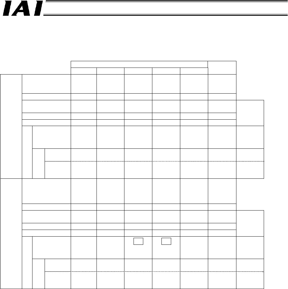
The table below lists the number of positions available for each controller in each PIO pattern, and the
corresponding maximum number of positions that can be registered for the Gateway Unit. Take note that
the number of positions may be limited in some cases.
PIO patterns (Parameter No. 25) SE
0 1 2 3 4
Operation type
Standard
Electro-
magnetic
valve type
Zone
signal
type
Position
zone type
-
Exclusive
to SIO
Positioning points 8 3 16 16 - 64
Home return
signal
{
x x x -
{
Zone signal
{
x
{
x -
{
P zone signal x x x
{
-
{
Maximum
Gateway
positions
Position-
number
specification
mode
8
*1
x
16
*1
16
*1
- 64 64
Positioner
operation
*1 *3
8 (0)
x
*1 *3
16 (2)
*1 *3
16 (3)
-
*3
64 (0)
512
ERC2
Gateway controls
Command
specification
Simple
direct
operation
- x - - - - 512
Operation type
Position-
ing
mode
Teaching
mode
256-point
mode
512-point
mode
Electro-
magnetic
valve
mode 1
Exclusive
to SIO
Positioning points 64 64 256 512 7 64
Home return
signal
{ { { { { {
Zone signal
{
x x x
{ {
P zone signal
{ { {
x
{ {
Maximum
Gateway
positions
Position-
number
specification
mode
64 64
256
↓
64 *2
512
↓
64 *2
7 64 64
Positioner
operation
*3
64 (0)
*3
64 (1)
*3
256 (2)
*3
512 (3)
*3
7 (4)
*3
64 (0)
512
PCON
ACON
SCON
Gateway controls
Command
specification
Simple
direct
operation
- - - - - - 512
*1 In an operation mode where position numbers are specified, the number of available positions is
limited according to the PIO pattern selected (via parameter No. 25). (The Gateway can handle a
greater number of positions.)
*2 Since the Gateway can handle 64 positions, the number of positions available for the controller is
limited.
*3 With positioner operation axes under the command specification mode, align the setting of the
controller’s PIO pattern selection parameter with the I/O pattern set by Gateway control signals PPS0
to PPS2. The value that should be set by PPS0 to PPS2 is shown in parentheses after the number of
positions.