
Manual
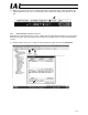


Table Of Contents
- 1. Overview
- 2. Specifications and Name of Each Part
- 2.1 General Specifications
- 2.2 External Dimensions
- 2.3 Name and Function of Each Part
- [1] Gateway status indicator LEDs
- [2] SIO communication status LEDs
- [3] Mode setting switch
- [4] External port switching input
- [5] Controller communication lines
- [6] DeviceNet communication connector
- [7] Baud-rate setting switches
- [8] Node-address setting switches
- [9] DeviceNet communication status LEDs
- [10] Port switch
- [11] Teaching pendant/PC connector
- [12] Power-supply input
- 3. Installation and Noise Elimination Measures
- 4. Wiring
- 4.1 Overall Configuration
- 4.2 I/O Signals of Gateway Unit
- 4.3 Design of SIO Communication Network (SIO Communication)
- 4.3.1 Wiring
- (1) Basics
- (2) Linking PCON/ACON/SCON controllers via SIO communication
- (3) Linking ERC2-SE controllers via SIO communication
- (4) Linking ERC2-NP/PN controllers via SIO communication
- (5) Wiring the emergency stop (EMG) circuit
- [1] Example of cutting off drive signals
- [2] Example of cutting off motor drive power
- 4.3.2 Axis Number Setting
- 4.3.1 Wiring
- 4.4 How to Connect Teaching Tools When Grounding the Positive Terminal of the 24-V Power Supply
- 5. Overview of DeviceNet
- 6. Address Configuration of Gateway Unit
- 7. Communication Signal Details
- 7.1 Overview of Communication Signal Timings
- 7.2 Communication Signals and Operation Timings
- (1) Controller ready (PWR)
- (2) Emergency stop (EMGS)
- (3) Alarm (ALM)
- (4) Reset (RES)
- (5) Pause (STP)
- (6) Moving (MOVE)
- (7) Servo ON command (SON)
- (8) Home return command (HOME)
- (9) Positioning start (CSTR)
- (10) Position complete (PEND)
- (11) Command position number (PC1 to PC512)
- (12) Completed position number (PM1 to PM256)
- (13) Zone (PZONE, ZONE1, ZONE2)
- (14) Jog + command/jog- command (JOG+/JOG-)
- (15) Jog/inching switching (JISL)
- (16) Teaching mode command (MOD)
- (17) Position data read command (PWRT)
- (18) Forced brake release (BKRL)
- 7.3 Basic Operation Timings
- 7.4 Command Transmission
- 8. Network System Building Procedure
- 8.1 Procedure
- 8.2 Settings for Controller Communication
- 8.3 Setting the Gateway Unit and PLC Master
- 8.4 Assigning the Master PLC Address by Free Assignment
- 8.5 Assigning the Master PLC Address by Fixed Assignment
- 9. Example of DeviceNet Operation
- 10. Troubleshooting
119
DeviceNet Gateway
9.2 Actuator Operation Pattern
Both linked axes 0 and 1 are operated in the position-number specification mode.
The operation pattern is specified below. Specifically, position No. 0 is specified to cause the actuator to
move to position No. 0 after completion of home return. The actuator pauses for 1 second in this position,
after which position No. 1 is specified to cause the actuator to move to position No. 1. The actuator
pauses for 1 second in this position, after which position No. 0 is specified. These steps are repeated to
make the actuator move back and forth between position Nos. 0 and 1.
9.3 Various Controller Settings
(1) Setting the axis number
Refer to 8.2.
(2) Setting the baud rate for SIO communication
Refer to 8.2.
(3) Creating a position table
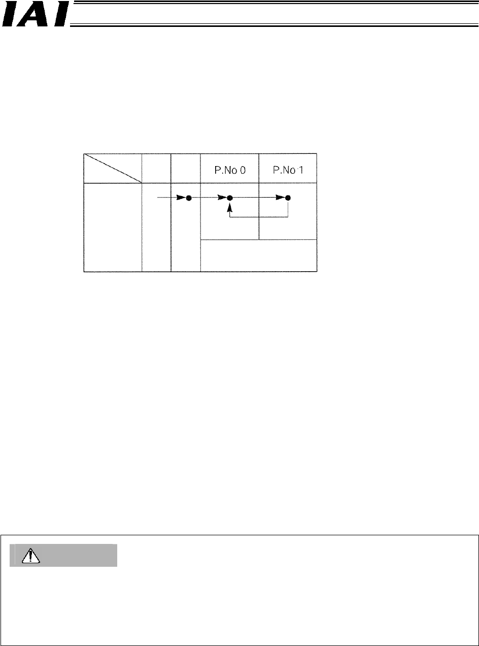
After (2), perform the following steps in the initial window of the PC software:
[1] Click Position (T), and then select Edit/Teach (E).
[2] Select axis 0, click >, and then click OK.
[3] When the position data edit window for axis 0 appears, enter the applicable data.
[4] Transfer the data to the controller, and then click X to close the edit window.
[5] Repeat steps [1] to [4] by selecting axis 1.
[6] Shut down the PC software.
[7] Remove the PC cable from the Gateway unit, and turn the port switch OFF.
Caution
After specifying any of the various settings pertaining to each SIO-linked axis or creating a position
table by connecting the PC (software) or teaching pendant to the Gateway Unit, always change the
MANU operation mode to <Monitor Mode 2> before shutting down the PC software or teaching
pendant.
Otherwise, the controller cannot be started from the PLC next time.
For details, refer to the operation manual for your PC software or teaching pendant.
A
xis
Position
Home
Linked axis 0
Linked axis 1
The actuator pauses for 1
second after completing
positioning.