
Manual
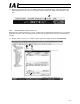


Table Of Contents
- 1. Overview
- 2. Specifications and Name of Each Part
- 2.1 General Specifications
- 2.2 External Dimensions
- 2.3 Name and Function of Each Part
- [1] Gateway status indicator LEDs
- [2] SIO communication status LEDs
- [3] Mode setting switch
- [4] External port switching input
- [5] Controller communication lines
- [6] DeviceNet communication connector
- [7] Baud-rate setting switches
- [8] Node-address setting switches
- [9] DeviceNet communication status LEDs
- [10] Port switch
- [11] Teaching pendant/PC connector
- [12] Power-supply input
- 3. Installation and Noise Elimination Measures
- 4. Wiring
- 4.1 Overall Configuration
- 4.2 I/O Signals of Gateway Unit
- 4.3 Design of SIO Communication Network (SIO Communication)
- 4.3.1 Wiring
- (1) Basics
- (2) Linking PCON/ACON/SCON controllers via SIO communication
- (3) Linking ERC2-SE controllers via SIO communication
- (4) Linking ERC2-NP/PN controllers via SIO communication
- (5) Wiring the emergency stop (EMG) circuit
- [1] Example of cutting off drive signals
- [2] Example of cutting off motor drive power
- 4.3.2 Axis Number Setting
- 4.3.1 Wiring
- 4.4 How to Connect Teaching Tools When Grounding the Positive Terminal of the 24-V Power Supply
- 5. Overview of DeviceNet
- 6. Address Configuration of Gateway Unit
- 7. Communication Signal Details
- 7.1 Overview of Communication Signal Timings
- 7.2 Communication Signals and Operation Timings
- (1) Controller ready (PWR)
- (2) Emergency stop (EMGS)
- (3) Alarm (ALM)
- (4) Reset (RES)
- (5) Pause (STP)
- (6) Moving (MOVE)
- (7) Servo ON command (SON)
- (8) Home return command (HOME)
- (9) Positioning start (CSTR)
- (10) Position complete (PEND)
- (11) Command position number (PC1 to PC512)
- (12) Completed position number (PM1 to PM256)
- (13) Zone (PZONE, ZONE1, ZONE2)
- (14) Jog + command/jog- command (JOG+/JOG-)
- (15) Jog/inching switching (JISL)
- (16) Teaching mode command (MOD)
- (17) Position data read command (PWRT)
- (18) Forced brake release (BKRL)
- 7.3 Basic Operation Timings
- 7.4 Command Transmission
- 8. Network System Building Procedure
- 8.1 Procedure
- 8.2 Settings for Controller Communication
- 8.3 Setting the Gateway Unit and PLC Master
- 8.4 Assigning the Master PLC Address by Free Assignment
- 8.5 Assigning the Master PLC Address by Fixed Assignment
- 9. Example of DeviceNet Operation
- 10. Troubleshooting

120
DeviceNet Gateway
9.4 Setting Up the Gateway Unit
(1) Setting the Gateway Unit mode
Since the actuators are operated in the position-number specification mode, set each position of the
mode setting switch (SW1) as follows:
1: OFF 2: ON 3: OFF 4: OFF
(2) Setting the node address and baud rate for the Gateway Unit
Node address = 0
Baud rate = 500 kbps (example)
To effect the above settings, set the DIP switches as follows:
DR1: ON DR2: OFF
NA1, 2, 4, 8, 16, 32: All OFF
9.5 Setting Up the DeviceNet Master Unit (CJ1W-DRM21)
(1) Setting the unit number
On the PLC, set “0” indicating a CPU high-function unit.
(2) Setting the node address
Set the master unit’s node address on the network to “63” to prevent duplication with other slaves
within the range of 0 to 63.
(3) Setting the baud rate, etc.
The baud rate is set to 500 kbps. Accordingly, set the DIP switches as follows:
1: OFF 2: ON 3: OFF 4: OFF
* For details, refer to the operation manual for your PLC.
9.6 Assigning the Master PLC Address
Each slave (gateway unit) must be assigned to an I/O memory area of the CPU unit in which the
master unit is installed.
This assignment is performed either by free assignment where the DeviceNet configurator is used to
automatically assign an I/O memory area, or by fixed assignment using CX-Programmer. (Refer to
8.4 and 8.5.)