
Manual
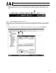


Table Of Contents
- 1. Overview
- 2. Specifications and Name of Each Part
- 2.1 General Specifications
- 2.2 External Dimensions
- 2.3 Name and Function of Each Part
- [1] Gateway status indicator LEDs
- [2] SIO communication status LEDs
- [3] Mode setting switch
- [4] External port switching input
- [5] Controller communication lines
- [6] DeviceNet communication connector
- [7] Baud-rate setting switches
- [8] Node-address setting switches
- [9] DeviceNet communication status LEDs
- [10] Port switch
- [11] Teaching pendant/PC connector
- [12] Power-supply input
- 3. Installation and Noise Elimination Measures
- 4. Wiring
- 4.1 Overall Configuration
- 4.2 I/O Signals of Gateway Unit
- 4.3 Design of SIO Communication Network (SIO Communication)
- 4.3.1 Wiring
- (1) Basics
- (2) Linking PCON/ACON/SCON controllers via SIO communication
- (3) Linking ERC2-SE controllers via SIO communication
- (4) Linking ERC2-NP/PN controllers via SIO communication
- (5) Wiring the emergency stop (EMG) circuit
- [1] Example of cutting off drive signals
- [2] Example of cutting off motor drive power
- 4.3.2 Axis Number Setting
- 4.3.1 Wiring
- 4.4 How to Connect Teaching Tools When Grounding the Positive Terminal of the 24-V Power Supply
- 5. Overview of DeviceNet
- 6. Address Configuration of Gateway Unit
- 7. Communication Signal Details
- 7.1 Overview of Communication Signal Timings
- 7.2 Communication Signals and Operation Timings
- (1) Controller ready (PWR)
- (2) Emergency stop (EMGS)
- (3) Alarm (ALM)
- (4) Reset (RES)
- (5) Pause (STP)
- (6) Moving (MOVE)
- (7) Servo ON command (SON)
- (8) Home return command (HOME)
- (9) Positioning start (CSTR)
- (10) Position complete (PEND)
- (11) Command position number (PC1 to PC512)
- (12) Completed position number (PM1 to PM256)
- (13) Zone (PZONE, ZONE1, ZONE2)
- (14) Jog + command/jog- command (JOG+/JOG-)
- (15) Jog/inching switching (JISL)
- (16) Teaching mode command (MOD)
- (17) Position data read command (PWRT)
- (18) Forced brake release (BKRL)
- 7.3 Basic Operation Timings
- 7.4 Command Transmission
- 8. Network System Building Procedure
- 8.1 Procedure
- 8.2 Settings for Controller Communication
- 8.3 Setting the Gateway Unit and PLC Master
- 8.4 Assigning the Master PLC Address by Free Assignment
- 8.5 Assigning the Master PLC Address by Fixed Assignment
- 9. Example of DeviceNet Operation
- 10. Troubleshooting

124
DeviceNet Gateway
10. Troubleshooting
10.1 Actions to Be Taken upon Problems
If you encountered a problem, follow the steps below to take appropriate actions in order to restore the
system quickly and prevent the same problem from occurring again:
a. Check the statuses of various LED indicators on the Gateway Unit.
[1] Gateway Unit status indicator LEDs (RUN, G.ER, C.ER, T.ER)
[2] SIO communication status LEDs (TxD, RxD)
[3] DeviceNet communication status LEDs (MS, NS)
b. Check the host controller (PLC, master station) for abnormality.
c. Check the controller for abnormality.
d. Check the power-supply voltage of the Gateway Unit.
e. Check the cables for contact problem, disconnection and pinching.
To check continuity, turn off the power and disconnect the wiring.
f. Check the noise elimination measures (connection of ground lines, installation of surge killers,
connection of terminal resistors on communication lines, etc.).
g. Check operations using the teaching pendant or PC software.
Connect the teaching pendant or PC software to the Gateway Unit and operate each axis to
check the operations and also see if any alarm generates.
h. Check the I/O signals transmitted between the PLC and the controller.
[1] Check the I/O signals of the PLC using the monitor function of the PC software CX-
Programmer (Omron product), etc.
[2] Check the I/O signals of the controller using the status monitor function of the PC software
or teaching pendant.
[3] Confirm that the signals checked in [1] and [2] above are consistent.
i. Check the events leading up to the problem, as well as the operating condition when the
problem occurred.
j. Analyze the cause.
k. Implement countermeasures.
Before contacting IAI, check the items specified in a through i and inform us of the results.