
Manual


Table Of Contents
- 1. Overview
- 2. Specifications and Name of Each Part
- 2.1 General Specifications
- 2.2 External Dimensions
- 2.3 Name and Function of Each Part
- [1] Gateway status indicator LEDs
- [2] SIO communication status LEDs
- [3] Mode setting switch
- [4] External port switching input
- [5] Controller communication lines
- [6] DeviceNet communication connector
- [7] Baud-rate setting switches
- [8] Node-address setting switches
- [9] DeviceNet communication status LEDs
- [10] Port switch
- [11] Teaching pendant/PC connector
- [12] Power-supply input
- 3. Installation and Noise Elimination Measures
- 4. Wiring
- 4.1 Overall Configuration
- 4.2 I/O Signals of Gateway Unit
- 4.3 Design of SIO Communication Network (SIO Communication)
- 4.3.1 Wiring
- (1) Basics
- (2) Linking PCON/ACON/SCON controllers via SIO communication
- (3) Linking ERC2-SE controllers via SIO communication
- (4) Linking ERC2-NP/PN controllers via SIO communication
- (5) Wiring the emergency stop (EMG) circuit
- [1] Example of cutting off drive signals
- [2] Example of cutting off motor drive power
- 4.3.2 Axis Number Setting
- 4.3.1 Wiring
- 4.4 How to Connect Teaching Tools When Grounding the Positive Terminal of the 24-V Power Supply
- 5. Overview of DeviceNet
- 6. Address Configuration of Gateway Unit
- 7. Communication Signal Details
- 7.1 Overview of Communication Signal Timings
- 7.2 Communication Signals and Operation Timings
- (1) Controller ready (PWR)
- (2) Emergency stop (EMGS)
- (3) Alarm (ALM)
- (4) Reset (RES)
- (5) Pause (STP)
- (6) Moving (MOVE)
- (7) Servo ON command (SON)
- (8) Home return command (HOME)
- (9) Positioning start (CSTR)
- (10) Position complete (PEND)
- (11) Command position number (PC1 to PC512)
- (12) Completed position number (PM1 to PM256)
- (13) Zone (PZONE, ZONE1, ZONE2)
- (14) Jog + command/jog- command (JOG+/JOG-)
- (15) Jog/inching switching (JISL)
- (16) Teaching mode command (MOD)
- (17) Position data read command (PWRT)
- (18) Forced brake release (BKRL)
- 7.3 Basic Operation Timings
- 7.4 Command Transmission
- 8. Network System Building Procedure
- 8.1 Procedure
- 8.2 Settings for Controller Communication
- 8.3 Setting the Gateway Unit and PLC Master
- 8.4 Assigning the Master PLC Address by Free Assignment
- 8.5 Assigning the Master PLC Address by Fixed Assignment
- 9. Example of DeviceNet Operation
- 10. Troubleshooting
127
DeviceNet Gateway
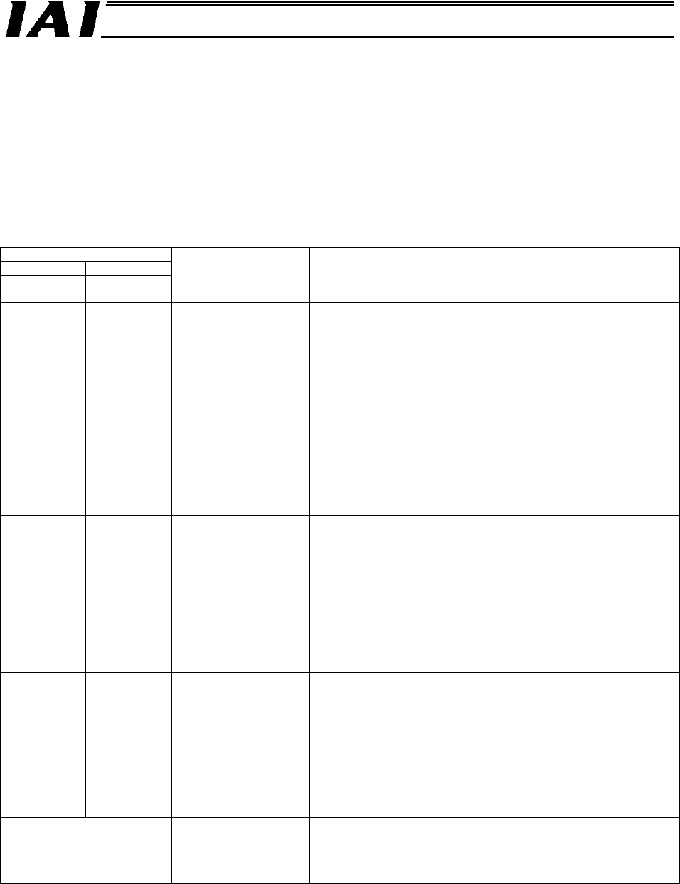
10.2.4 Troubleshooting for DeviceNet Communication
If you encountered a problem with DeviceNet, check the operating condition and remove the cause
by referring to the table below. The monitor LEDs illuminate in two different colors (red/green). The
statues of these indicators can be used to check the DeviceNet status.
If an error occurs, the MS or NS LED will illuminate or blink in red. If you find a blinking or steady red
LED, check the connections of power-supply and communication cables and also check (reset) the
baud-rate and node-address setting switches once again, and then reconnect the power.
: Steady light, : Unlit, X: Blinking
Monitor LEDs
MS NS
Green Red Green Red
Status Countermeasure
{
-
{
- Normal
{
-
z z
Waiting for the node
address duplication
check to be completed by
the master
Check if the baud rate of the master matches the baud rates of all
slaves. If any inappropriate setting is found, make the necessary
correction and then restart the system.
Check if the connectors are properly engaged.
Check if the communication power (24 VDC) is supplied. *1
Check if the master is operating correctly.
Check the communication cables for disconnection. *1
{
-
- Waiting for connection to
be established with the
master
Check if the master is operating correctly.
Check if the slave is registered in the scan list of the master.
-
{ z z
Hardware error Contact IAI. (The DeviceNet board may have to be replaced.)
-
z z
DIP switch setting error
Check if the baud rate of the slave matches the baud rate of the
master.
Check if all items are configured correctly.
If any inappropriate setting is found, make the necessary correction
and then restart the system.
{
- -
{
Detection of duplicate
node addresses or “bus
off” (halting of
communication due to
frequent data errors)
Correct the node address(es) and then restart the system.
Check if the baud rate of the slave matches the baud rate of the
master.
Check if the communication cable length is appropriate. *1
Check the communication cables for disconnection or loose or
disconnected connector. *1
Check if the terminal resistors are installed correctly. *1
Check for possible effect of noise, such as presence of noise
sources nearby or power lines running in parallel with the
communication cables. *1, *2
If any inappropriate setting is found, make the necessary correction
and then restart the system.
{
- -
Communication time out
Check if the baud rate of the slave matches the baud rate of the
master.
Check if the communication cable length is appropriate. *1
Check the communication cables for disconnection or loose or
disconnected connector. *1
Check if the terminal resistors are installed correctly. *1
Check for possible effect of noise, such as presence of noise
sources nearby or power lines running in parallel with the
communication cables. *1, *2
If any inappropriate setting is found, make the necessary correction
and then restart the system.
The NS LED alternates between
steady green and blinking
green, or the NS LED alternates
between blinking red and
blinking green.
Communication error Check if the slave is registered in the scan list of the master.
Check the I/O areas for duplicate assignment to other slave.
Check the I/O areas for overflow beyond the areas permitted by the
master unit (in the case of fixed assignment).
*1 A problem is suspected in the DeviceNet communication cable or DeviceNet power supply. Check
4.1, “Overall Wiring Configuration.”