
Manual


Table Of Contents
- 1. Overview
- 2. Specifications and Name of Each Part
- 2.1 General Specifications
- 2.2 External Dimensions
- 2.3 Name and Function of Each Part
- [1] Gateway status indicator LEDs
- [2] SIO communication status LEDs
- [3] Mode setting switch
- [4] External port switching input
- [5] Controller communication lines
- [6] DeviceNet communication connector
- [7] Baud-rate setting switches
- [8] Node-address setting switches
- [9] DeviceNet communication status LEDs
- [10] Port switch
- [11] Teaching pendant/PC connector
- [12] Power-supply input
- 3. Installation and Noise Elimination Measures
- 4. Wiring
- 4.1 Overall Configuration
- 4.2 I/O Signals of Gateway Unit
- 4.3 Design of SIO Communication Network (SIO Communication)
- 4.3.1 Wiring
- (1) Basics
- (2) Linking PCON/ACON/SCON controllers via SIO communication
- (3) Linking ERC2-SE controllers via SIO communication
- (4) Linking ERC2-NP/PN controllers via SIO communication
- (5) Wiring the emergency stop (EMG) circuit
- [1] Example of cutting off drive signals
- [2] Example of cutting off motor drive power
- 4.3.2 Axis Number Setting
- 4.3.1 Wiring
- 4.4 How to Connect Teaching Tools When Grounding the Positive Terminal of the 24-V Power Supply
- 5. Overview of DeviceNet
- 6. Address Configuration of Gateway Unit
- 7. Communication Signal Details
- 7.1 Overview of Communication Signal Timings
- 7.2 Communication Signals and Operation Timings
- (1) Controller ready (PWR)
- (2) Emergency stop (EMGS)
- (3) Alarm (ALM)
- (4) Reset (RES)
- (5) Pause (STP)
- (6) Moving (MOVE)
- (7) Servo ON command (SON)
- (8) Home return command (HOME)
- (9) Positioning start (CSTR)
- (10) Position complete (PEND)
- (11) Command position number (PC1 to PC512)
- (12) Completed position number (PM1 to PM256)
- (13) Zone (PZONE, ZONE1, ZONE2)
- (14) Jog + command/jog- command (JOG+/JOG-)
- (15) Jog/inching switching (JISL)
- (16) Teaching mode command (MOD)
- (17) Position data read command (PWRT)
- (18) Forced brake release (BKRL)
- 7.3 Basic Operation Timings
- 7.4 Command Transmission
- 8. Network System Building Procedure
- 8.1 Procedure
- 8.2 Settings for Controller Communication
- 8.3 Setting the Gateway Unit and PLC Master
- 8.4 Assigning the Master PLC Address by Free Assignment
- 8.5 Assigning the Master PLC Address by Fixed Assignment
- 9. Example of DeviceNet Operation
- 10. Troubleshooting
DeviceNet Gateway
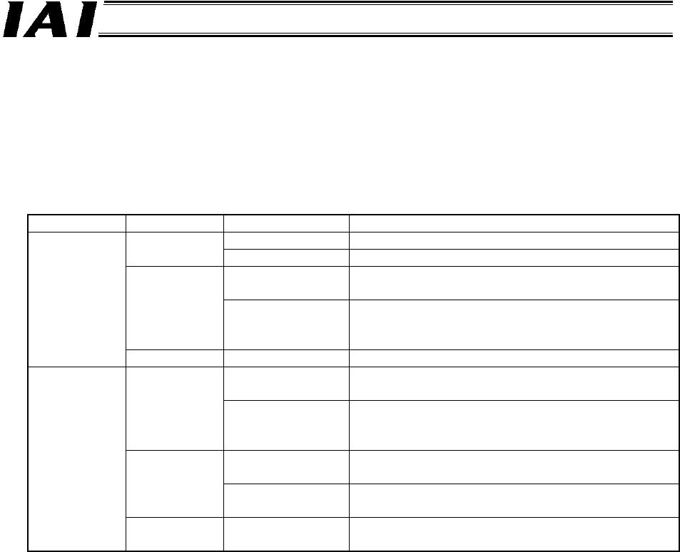
[9] DeviceNet communication status LEDs
The two LEDs of MS and NS on the front face of the board indicate the node status and network
status. (The remaining two LEDs are not used.)
These LEDs illuminate in one of two colors (red or green), and each LED indicates a different
monitored status, as shown in the table below.
MS (Module Status) LED ..... This LED indicates the status of the node.
NS (Network Status) LED ..... This LED indicates the status of the network.
LED Color Indicated status Description (meaning of indication)
Lit The node is operating normally. Green
Blink The specified data size is exceeded.
Lit A hardware error is present. The board must be
replaced.
Red
Blink
A
minor error, such as a DIP switch setting error or
configuration error, is present. A normal condition
can be restored by a reset operation, etc.
MS
- Unlit The power is not supplied.
Lit Network connection has been established and
communication is in progress without problem.
Green
Blink The node is online, but network connection is not
yet established. Communication is stopped. (The
network is normal.)
Lit A fatal error, such as duplicate node addresses or
“bus off,” is present. Communication is disabled.
Red
Blink A communication error is present.
(A communication timeout occurred.)
NS
- Unlit • The node is offline.
• The power is not supplied.
The node performs self-test when the power is input.
During the self-test, the monitor LEDs change their indications in the following sequence:
[1] The NS LED turns off.
[2] The MS LED illuminates in steady green (for approx. 0.25 second).
[3] The MS LED illuminates in steady red (for approx. 0.25 second).
[4] The MS LED illuminates in steady green.
[5] The NS LED illuminates in steady green (for approx. 0.25 second).
[6] The NS LED illuminates in steady red (for approx. 0.25 second).
[7] The NS LED turns off.
When the self-test is completed and communication starts successfully, both the MS and NS LEDs
will change to steady green.