
Manual


Table Of Contents
- 1. Overview
- 2. Specifications and Name of Each Part
- 2.1 General Specifications
- 2.2 External Dimensions
- 2.3 Name and Function of Each Part
- [1] Gateway status indicator LEDs
- [2] SIO communication status LEDs
- [3] Mode setting switch
- [4] External port switching input
- [5] Controller communication lines
- [6] DeviceNet communication connector
- [7] Baud-rate setting switches
- [8] Node-address setting switches
- [9] DeviceNet communication status LEDs
- [10] Port switch
- [11] Teaching pendant/PC connector
- [12] Power-supply input
- 3. Installation and Noise Elimination Measures
- 4. Wiring
- 4.1 Overall Configuration
- 4.2 I/O Signals of Gateway Unit
- 4.3 Design of SIO Communication Network (SIO Communication)
- 4.3.1 Wiring
- (1) Basics
- (2) Linking PCON/ACON/SCON controllers via SIO communication
- (3) Linking ERC2-SE controllers via SIO communication
- (4) Linking ERC2-NP/PN controllers via SIO communication
- (5) Wiring the emergency stop (EMG) circuit
- [1] Example of cutting off drive signals
- [2] Example of cutting off motor drive power
- 4.3.2 Axis Number Setting
- 4.3.1 Wiring
- 4.4 How to Connect Teaching Tools When Grounding the Positive Terminal of the 24-V Power Supply
- 5. Overview of DeviceNet
- 6. Address Configuration of Gateway Unit
- 7. Communication Signal Details
- 7.1 Overview of Communication Signal Timings
- 7.2 Communication Signals and Operation Timings
- (1) Controller ready (PWR)
- (2) Emergency stop (EMGS)
- (3) Alarm (ALM)
- (4) Reset (RES)
- (5) Pause (STP)
- (6) Moving (MOVE)
- (7) Servo ON command (SON)
- (8) Home return command (HOME)
- (9) Positioning start (CSTR)
- (10) Position complete (PEND)
- (11) Command position number (PC1 to PC512)
- (12) Completed position number (PM1 to PM256)
- (13) Zone (PZONE, ZONE1, ZONE2)
- (14) Jog + command/jog- command (JOG+/JOG-)
- (15) Jog/inching switching (JISL)
- (16) Teaching mode command (MOD)
- (17) Position data read command (PWRT)
- (18) Forced brake release (BKRL)
- 7.3 Basic Operation Timings
- 7.4 Command Transmission
- 8. Network System Building Procedure
- 8.1 Procedure
- 8.2 Settings for Controller Communication
- 8.3 Setting the Gateway Unit and PLC Master
- 8.4 Assigning the Master PLC Address by Free Assignment
- 8.5 Assigning the Master PLC Address by Fixed Assignment
- 9. Example of DeviceNet Operation
- 10. Troubleshooting
DeviceNet Gateway
DeviceNet unit (master)
Node
Terminal
resistors are
installed.
Branch line
T-junction tap
Main line
24-VDC
communication
power supply
Terminal
resistors are
installed.
Node
Node
NodeNode
Node
Node Node Node
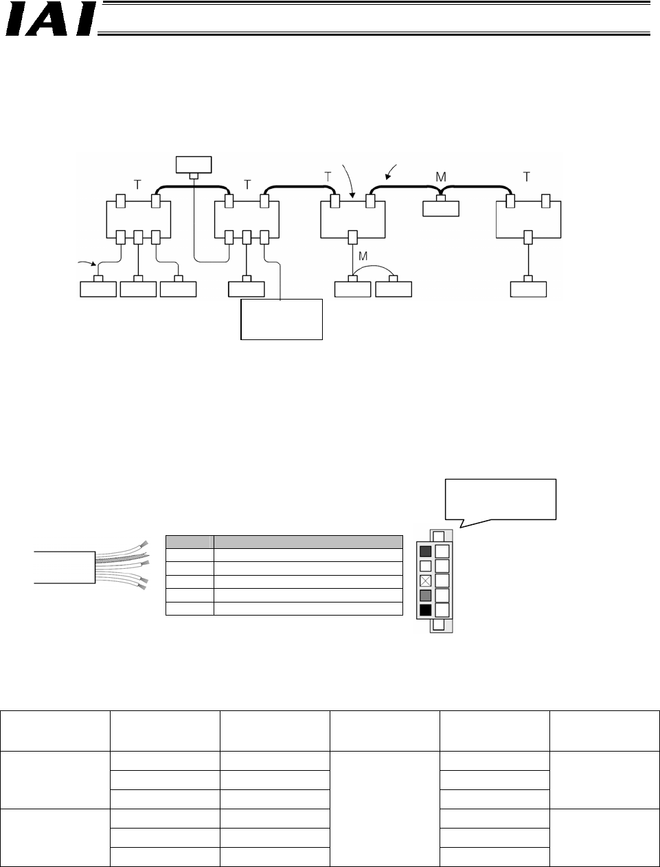
DeviceNet network wiring is shown below.
For details on DeviceNet, refer to the operation manual for the master (PLC).
Shown below is an example of the DeviceNet network.
(1) A device with an address connected to the network is called “node.” A node may be a master
(DeviceNet unit in the figure above) that manages DeviceNet, or a slave that connects an
external I/O. Masters and slaves can be arranged in any positions.
(2) A cable having a terminal resistor installed on both ends is called “main line” (thick line in the
figure), while a cable branching from a main line is called “branch line” (thin line in the figure).
Both cables use the dedicated five-lead DeviceNet cable. Either the thick cable or thin cable is
used depending on the supplied current.
You can learn more about this dedicated cable on the ODVA website.
The dedicated cable is shown below.
Color Signal type
Red Power-supply cable + (V+)
White Communication data high (CAN H)
- Shield
Blue Communication data low (CAN L)
Black Power-supply cable - (V-)
How to Determine Which Cable to Use
The table below summarizes the differences between thick and thin cables.
Type Baud rate
Maximum
network length
Branch length
Total branch
length
Current capacity
500 kbps 100 m 39 m
250 kbps 250 m 78 m
Thick cable
125 kbps 500 m 156 m
8 A
500 kbps 100 m 39 m
250 kbps 100 m 78 m
Thin cable
125 kbps 100 m
6 m
156 m
3 A
The wire colors are
also printed on the
dedicated connector.