
Manual


Table Of Contents
- 1. Overview
- 2. Specifications and Name of Each Part
- 2.1 General Specifications
- 2.2 External Dimensions
- 2.3 Name and Function of Each Part
- [1] Gateway status indicator LEDs
- [2] SIO communication status LEDs
- [3] Mode setting switch
- [4] External port switching input
- [5] Controller communication lines
- [6] DeviceNet communication connector
- [7] Baud-rate setting switches
- [8] Node-address setting switches
- [9] DeviceNet communication status LEDs
- [10] Port switch
- [11] Teaching pendant/PC connector
- [12] Power-supply input
- 3. Installation and Noise Elimination Measures
- 4. Wiring
- 4.1 Overall Configuration
- 4.2 I/O Signals of Gateway Unit
- 4.3 Design of SIO Communication Network (SIO Communication)
- 4.3.1 Wiring
- (1) Basics
- (2) Linking PCON/ACON/SCON controllers via SIO communication
- (3) Linking ERC2-SE controllers via SIO communication
- (4) Linking ERC2-NP/PN controllers via SIO communication
- (5) Wiring the emergency stop (EMG) circuit
- [1] Example of cutting off drive signals
- [2] Example of cutting off motor drive power
- 4.3.2 Axis Number Setting
- 4.3.1 Wiring
- 4.4 How to Connect Teaching Tools When Grounding the Positive Terminal of the 24-V Power Supply
- 5. Overview of DeviceNet
- 6. Address Configuration of Gateway Unit
- 7. Communication Signal Details
- 7.1 Overview of Communication Signal Timings
- 7.2 Communication Signals and Operation Timings
- (1) Controller ready (PWR)
- (2) Emergency stop (EMGS)
- (3) Alarm (ALM)
- (4) Reset (RES)
- (5) Pause (STP)
- (6) Moving (MOVE)
- (7) Servo ON command (SON)
- (8) Home return command (HOME)
- (9) Positioning start (CSTR)
- (10) Position complete (PEND)
- (11) Command position number (PC1 to PC512)
- (12) Completed position number (PM1 to PM256)
- (13) Zone (PZONE, ZONE1, ZONE2)
- (14) Jog + command/jog- command (JOG+/JOG-)
- (15) Jog/inching switching (JISL)
- (16) Teaching mode command (MOD)
- (17) Position data read command (PWRT)
- (18) Forced brake release (BKRL)
- 7.3 Basic Operation Timings
- 7.4 Command Transmission
- 8. Network System Building Procedure
- 8.1 Procedure
- 8.2 Settings for Controller Communication
- 8.3 Setting the Gateway Unit and PLC Master
- 8.4 Assigning the Master PLC Address by Free Assignment
- 8.5 Assigning the Master PLC Address by Fixed Assignment
- 9. Example of DeviceNet Operation
- 10. Troubleshooting
DeviceNet Gateway
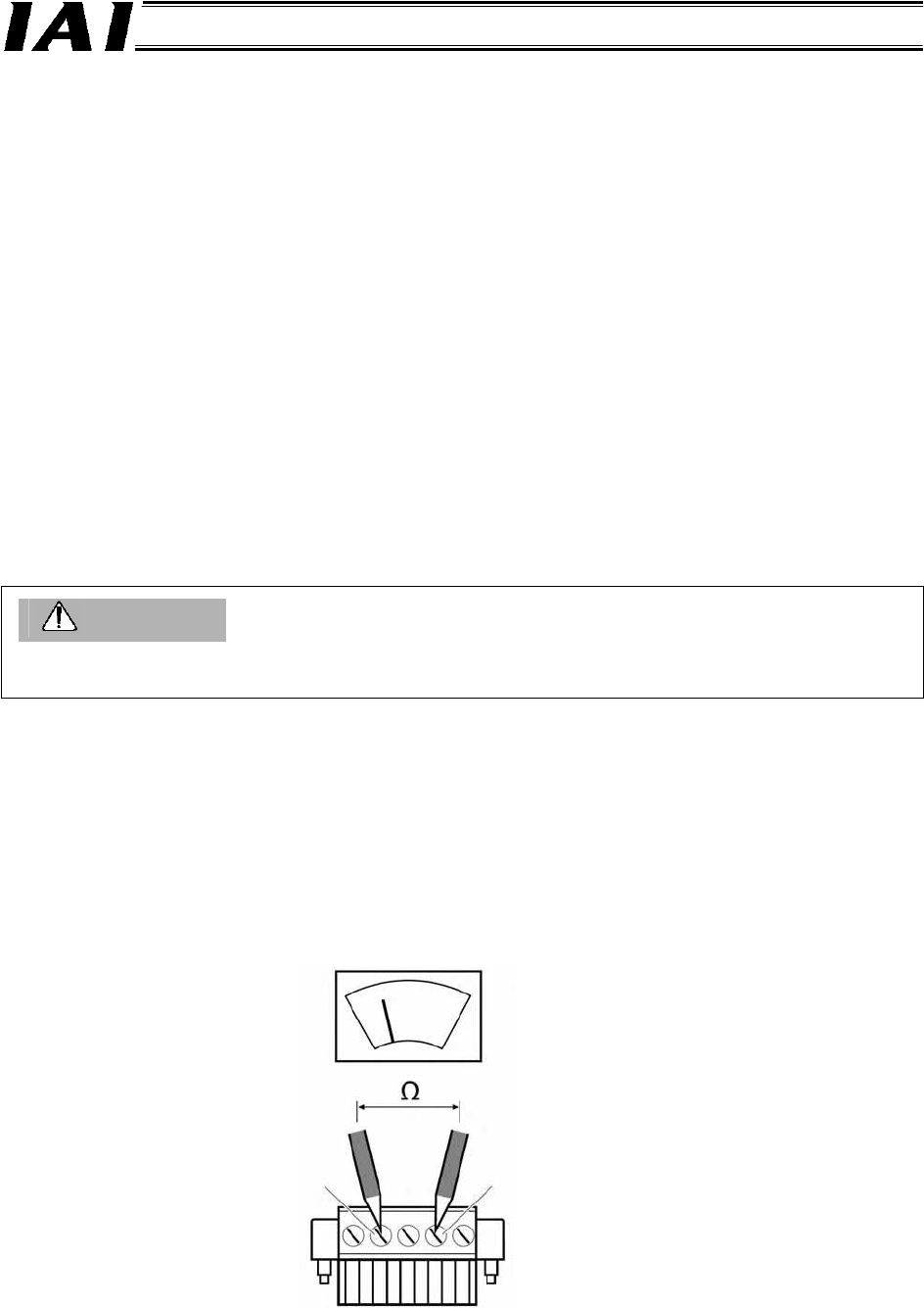
Tester
Use a tester to measure the
resistance between the signal lines.
White (CAN H)
Blue (CAN L)
About Grounding
• Do not ground the shield wires at multiple locations on the network. Always ground the shield wires at
one location.
• Provide dedicated grounding separately from the inverters for drive systems, etc.
(3) Nodes can be connected in one of two ways. Both methods can be employed together in a
single network.
[1] T-junction method --- A T-junction tap, etc., is used (Indicated by “T” in the network
diagram on p. 20)
[2] Multi-drop method --- A multi-drop connector is used to directly branch the cable at a node
(Indicated by “M” in the network diagram on p. 20)
(4) The communication power (24 VDC) must be supplied to each node via a five-lead cable.
With a DeviceNet system, the communication power (24 VDC) must be supplied to the network.
(5) A terminal resistor must be installed on both ends of a main line.
The gateway unit does not come with a terminal resistor.
Use a terminal-block type terminal resistor (121 Ω ±1%, 1/4 W) or T-branch tap with terminal
resistor (121 Ω ±1%, 1/4 W) by Omron, or connect other resistor of the same specification
directly between the white and blue terminals on the communication connector.
(6) The baud rate is limited in accordance with the network lengths (total branch line length and
maximum network length).
Caution
Align the ground potential level of the power supply of each controller connected to the Gateway Unit
with the ground potential level of the power supply of the Gateway Unit.
(7) When the wiring is complete, turn off the power and use a tester to measure the resistance
between the signal lines CAN H (white) and CAN L (blue) at any node.
• If the measured resistance is between 50 and 70 Ω, the connection is appropriate.
• If the measured resistance is 70 Ω or higher, the signal wires are open at some point or
there are not enough terminal resistors. This situation is classified as follows. If the
measured resistance is around 100 Ω, there is only one terminal resistance on the network.
If the measured resistor is 300 Ω or more, there is no terminal resistor on the network.
• If the measured resistance is less than 50 Ω, on the other hand, there are too many terminal
resistors. To be specific, there are at least three terminal resistors on the network.
Do not measure resistance while the system is operating, because it may cause communication data
errors, resulting in an unexpected accident.