
Manual


Table Of Contents
- 1. Overview
- 2. Specifications and Name of Each Part
- 2.1 General Specifications
- 2.2 External Dimensions
- 2.3 Name and Function of Each Part
- [1] Gateway status indicator LEDs
- [2] SIO communication status LEDs
- [3] Mode setting switch
- [4] External port switching input
- [5] Controller communication lines
- [6] DeviceNet communication connector
- [7] Baud-rate setting switches
- [8] Node-address setting switches
- [9] DeviceNet communication status LEDs
- [10] Port switch
- [11] Teaching pendant/PC connector
- [12] Power-supply input
- 3. Installation and Noise Elimination Measures
- 4. Wiring
- 4.1 Overall Configuration
- 4.2 I/O Signals of Gateway Unit
- 4.3 Design of SIO Communication Network (SIO Communication)
- 4.3.1 Wiring
- (1) Basics
- (2) Linking PCON/ACON/SCON controllers via SIO communication
- (3) Linking ERC2-SE controllers via SIO communication
- (4) Linking ERC2-NP/PN controllers via SIO communication
- (5) Wiring the emergency stop (EMG) circuit
- [1] Example of cutting off drive signals
- [2] Example of cutting off motor drive power
- 4.3.2 Axis Number Setting
- 4.3.1 Wiring
- 4.4 How to Connect Teaching Tools When Grounding the Positive Terminal of the 24-V Power Supply
- 5. Overview of DeviceNet
- 6. Address Configuration of Gateway Unit
- 7. Communication Signal Details
- 7.1 Overview of Communication Signal Timings
- 7.2 Communication Signals and Operation Timings
- (1) Controller ready (PWR)
- (2) Emergency stop (EMGS)
- (3) Alarm (ALM)
- (4) Reset (RES)
- (5) Pause (STP)
- (6) Moving (MOVE)
- (7) Servo ON command (SON)
- (8) Home return command (HOME)
- (9) Positioning start (CSTR)
- (10) Position complete (PEND)
- (11) Command position number (PC1 to PC512)
- (12) Completed position number (PM1 to PM256)
- (13) Zone (PZONE, ZONE1, ZONE2)
- (14) Jog + command/jog- command (JOG+/JOG-)
- (15) Jog/inching switching (JISL)
- (16) Teaching mode command (MOD)
- (17) Position data read command (PWRT)
- (18) Forced brake release (BKRL)
- 7.3 Basic Operation Timings
- 7.4 Command Transmission
- 8. Network System Building Procedure
- 8.1 Procedure
- 8.2 Settings for Controller Communication
- 8.3 Setting the Gateway Unit and PLC Master
- 8.4 Assigning the Master PLC Address by Free Assignment
- 8.5 Assigning the Master PLC Address by Fixed Assignment
- 9. Example of DeviceNet Operation
- 10. Troubleshooting
25
DeviceNet Gateway
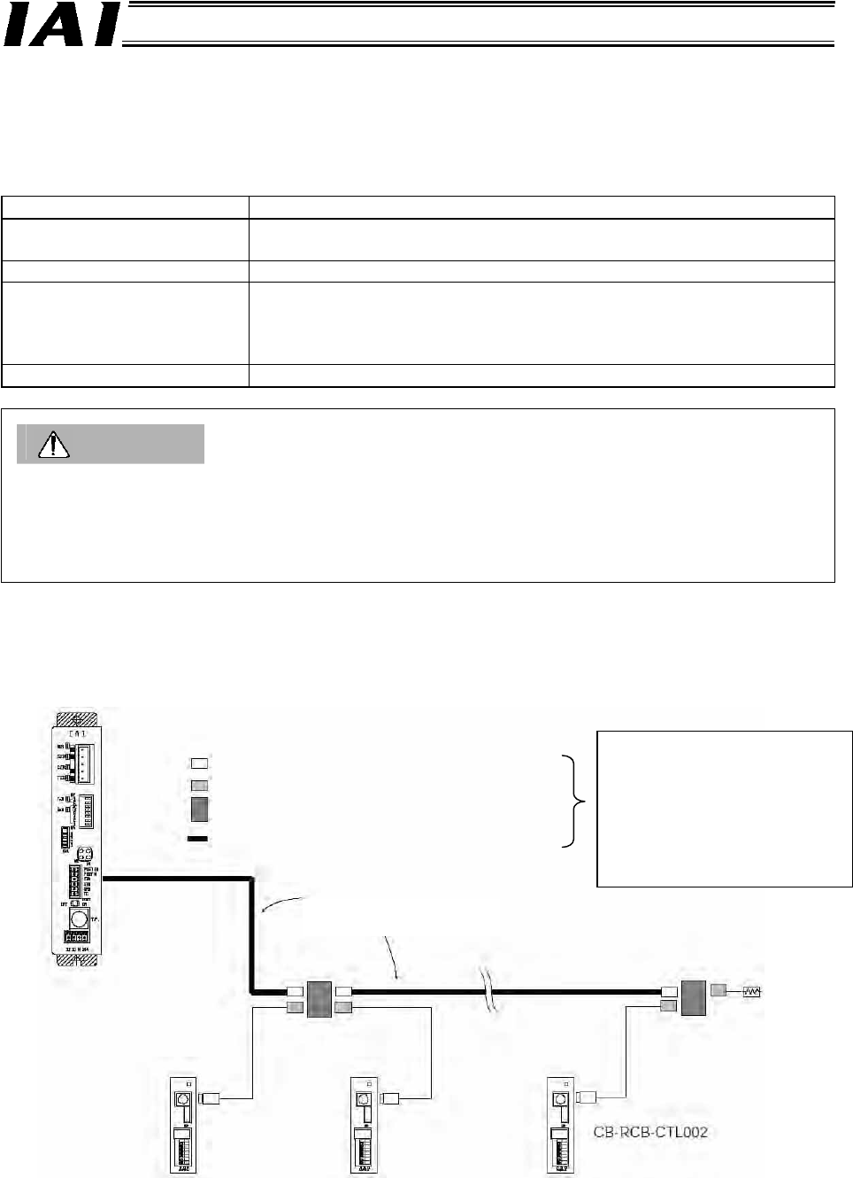
Gateway Unit
(Built-in terminal resistor)
SIO communication trunk
(Provided by the customer)
e-CON connector (4-1473562-4 by AMP, green)
e-CON connector (3-1473562-4 by AMP, orange)
Junction (5-1473574-4 by AMP)
Recommended cable: HK-SB/20276 X L 2P X AWG22
A
xis 1
A
xis 2
A
xis n
Controller link cable
Terminal resistor*1
R=220 Ω
1/4 W
You can use a terminal block or
directly connect the cables
using a joint without problem.
For the connection method,
refer to the detailed connection
diagram [Connection by
Terminal Block or Joint].
4.3 Design of SIO Communication Network (SIO Communication)
4.3.1 Wiring
(1) Basics
Item Description
Number of connected units
16 axes max. (The specific number varies depending on the operation
mode. Refer to 1.4, “Features of Gateway Unit.”)
Communication cable length Total cable length: 100 m max.
Communication cable
Double shielded twisted-pair cable (AWG22 --- Outer sheath diameter
1.35 to 1.60))
Recommended cable: HK-SB/20276 X L 2P X AWG22
by Taiyo Electric Wire & Cable
Terminal resistor
220 Ω 1/4 W
Caution
1. Connect the communication path to a bus and always connect a terminal resistor at the end. A
terminal resistor is not needed on the Gateway Unit end, as the unit has a built-in terminal resistor.
2. The customer must provide the communication cable. If the recommended cable is not used, make
sure the size of the cable to be used is AWG22.
(2) Linking PCON/ACON/SCON controllers via SIO communication
If the wiring receives tension or the IAI-recommended cable or equivalent is not used, it is
recommended that you use a terminal block or joint to perform the wiring without using the
connector. If the Gateway Unit connector receives tension, secure the cable nearby using a
mounting base, tie-band, etc.
*1 The terminal resistor (220 Ω,1/4 W) is supplied with the controller link cable.