
Manual


Table Of Contents
- 1. Overview
- 2. Specifications and Name of Each Part
- 2.1 General Specifications
- 2.2 External Dimensions
- 2.3 Name and Function of Each Part
- [1] Gateway status indicator LEDs
- [2] SIO communication status LEDs
- [3] Mode setting switch
- [4] External port switching input
- [5] Controller communication lines
- [6] DeviceNet communication connector
- [7] Baud-rate setting switches
- [8] Node-address setting switches
- [9] DeviceNet communication status LEDs
- [10] Port switch
- [11] Teaching pendant/PC connector
- [12] Power-supply input
- 3. Installation and Noise Elimination Measures
- 4. Wiring
- 4.1 Overall Configuration
- 4.2 I/O Signals of Gateway Unit
- 4.3 Design of SIO Communication Network (SIO Communication)
- 4.3.1 Wiring
- (1) Basics
- (2) Linking PCON/ACON/SCON controllers via SIO communication
- (3) Linking ERC2-SE controllers via SIO communication
- (4) Linking ERC2-NP/PN controllers via SIO communication
- (5) Wiring the emergency stop (EMG) circuit
- [1] Example of cutting off drive signals
- [2] Example of cutting off motor drive power
- 4.3.2 Axis Number Setting
- 4.3.1 Wiring
- 4.4 How to Connect Teaching Tools When Grounding the Positive Terminal of the 24-V Power Supply
- 5. Overview of DeviceNet
- 6. Address Configuration of Gateway Unit
- 7. Communication Signal Details
- 7.1 Overview of Communication Signal Timings
- 7.2 Communication Signals and Operation Timings
- (1) Controller ready (PWR)
- (2) Emergency stop (EMGS)
- (3) Alarm (ALM)
- (4) Reset (RES)
- (5) Pause (STP)
- (6) Moving (MOVE)
- (7) Servo ON command (SON)
- (8) Home return command (HOME)
- (9) Positioning start (CSTR)
- (10) Position complete (PEND)
- (11) Command position number (PC1 to PC512)
- (12) Completed position number (PM1 to PM256)
- (13) Zone (PZONE, ZONE1, ZONE2)
- (14) Jog + command/jog- command (JOG+/JOG-)
- (15) Jog/inching switching (JISL)
- (16) Teaching mode command (MOD)
- (17) Position data read command (PWRT)
- (18) Forced brake release (BKRL)
- 7.3 Basic Operation Timings
- 7.4 Command Transmission
- 8. Network System Building Procedure
- 8.1 Procedure
- 8.2 Settings for Controller Communication
- 8.3 Setting the Gateway Unit and PLC Master
- 8.4 Assigning the Master PLC Address by Free Assignment
- 8.5 Assigning the Master PLC Address by Fixed Assignment
- 9. Example of DeviceNet Operation
- 10. Troubleshooting
37
DeviceNet Gateway
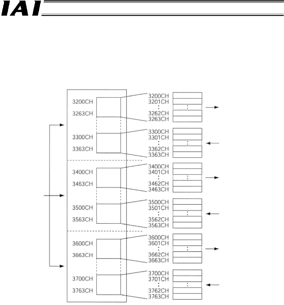
(1) Fixed assignment
When a CJ-series master unit is used, one of three pairs of fixed assignment areas can be specified
as assigned relay areas (using a specified soft switch).
In other words, three master units can be installed in a single PLC, with each master unit assigned
different areas.
[1] When areas are selected for fixed assignment, I/O addresses in the applicable output and input
areas will be assigned sequentially in the order of node addresses according to a fixed order.
[2] A slave having more than 16 I/O points occupies multiple channels.
[3] A slave having no more than 16 I/O points occupies the lower byte.
[4] The master unit will not occupy any channels even when the node address is set. (This applies
to both fixed assignment and free assignment.)
One of these
area pairs is
selected.
I/O memory address of
CPU unit
Output
(OUT)
area 1
Input
(IN)
area 1
Node address
To each slave
Address 0
Address 1
Address 62
Address 63
From each slave
Output
(OUT)
area 2
Input
(IN)
area 2
Output
(OUT)
area 3
Input
(IN)
area 3
Address 0
Address 1
Address 62
Address 63
Address 0
Address 1
Address 62
Address 63
Address 0
Address 1
Address 62
Address 63
Address 0
Address 1
Address 62
Address 63
Address 0
Address 1
Address 62
Address 63
To each slave
From each slave
To each slave
From each slave