
Manual


Table Of Contents
- 1. Overview
- 2. Specifications and Name of Each Part
- 2.1 General Specifications
- 2.2 External Dimensions
- 2.3 Name and Function of Each Part
- [1] Gateway status indicator LEDs
- [2] SIO communication status LEDs
- [3] Mode setting switch
- [4] External port switching input
- [5] Controller communication lines
- [6] DeviceNet communication connector
- [7] Baud-rate setting switches
- [8] Node-address setting switches
- [9] DeviceNet communication status LEDs
- [10] Port switch
- [11] Teaching pendant/PC connector
- [12] Power-supply input
- 3. Installation and Noise Elimination Measures
- 4. Wiring
- 4.1 Overall Configuration
- 4.2 I/O Signals of Gateway Unit
- 4.3 Design of SIO Communication Network (SIO Communication)
- 4.3.1 Wiring
- (1) Basics
- (2) Linking PCON/ACON/SCON controllers via SIO communication
- (3) Linking ERC2-SE controllers via SIO communication
- (4) Linking ERC2-NP/PN controllers via SIO communication
- (5) Wiring the emergency stop (EMG) circuit
- [1] Example of cutting off drive signals
- [2] Example of cutting off motor drive power
- 4.3.2 Axis Number Setting
- 4.3.1 Wiring
- 4.4 How to Connect Teaching Tools When Grounding the Positive Terminal of the 24-V Power Supply
- 5. Overview of DeviceNet
- 6. Address Configuration of Gateway Unit
- 7. Communication Signal Details
- 7.1 Overview of Communication Signal Timings
- 7.2 Communication Signals and Operation Timings
- (1) Controller ready (PWR)
- (2) Emergency stop (EMGS)
- (3) Alarm (ALM)
- (4) Reset (RES)
- (5) Pause (STP)
- (6) Moving (MOVE)
- (7) Servo ON command (SON)
- (8) Home return command (HOME)
- (9) Positioning start (CSTR)
- (10) Position complete (PEND)
- (11) Command position number (PC1 to PC512)
- (12) Completed position number (PM1 to PM256)
- (13) Zone (PZONE, ZONE1, ZONE2)
- (14) Jog + command/jog- command (JOG+/JOG-)
- (15) Jog/inching switching (JISL)
- (16) Teaching mode command (MOD)
- (17) Position data read command (PWRT)
- (18) Forced brake release (BKRL)
- 7.3 Basic Operation Timings
- 7.4 Command Transmission
- 8. Network System Building Procedure
- 8.1 Procedure
- 8.2 Settings for Controller Communication
- 8.3 Setting the Gateway Unit and PLC Master
- 8.4 Assigning the Master PLC Address by Free Assignment
- 8.5 Assigning the Master PLC Address by Fixed Assignment
- 9. Example of DeviceNet Operation
- 10. Troubleshooting
38
DeviceNet Gateway
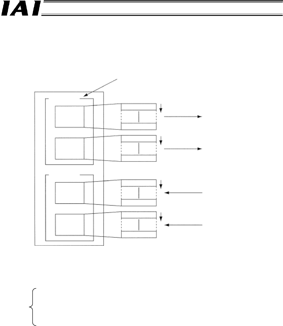
(2) Free assignment using a configurator
By using a DeviceNet configurator, slaves can be assigned respectively to four blocks, including
output area blocks 1 and 2 and input area blocks 1 and 2, in a desired node address order within
each block. By using this free assignment function, up to 16 master units can be installed in a single
PLC.
[1] One block has a maximum of 500 channels (i.e., there are 500 output channels x 2 and 500
input channels x 2). Each item can be assigned in desired areas within the applicable range
specified below:
I/O relay: 0000~6143CH
Internal auxiliary relay: W000~W511CH
Keep relay: H000~H511CH
Data memory: D00000~D32767
Expansion data memory: E00000~E32767
[2] The blocks can be assigned in a desired order, and the assigned block areas and node
addresses in each block can also be sequenced freely.
[3] A slave having more than 16 I/O points occupies multiple channels.
[4] A slave having no more than 16 I/O points occupies either the lower byte or upper byte.
*1 DeviceNet configurator
A software program for building, setting and managing DeviceNet networks using graphical screen
interfaces. This software provides the following functions:
• Free assignment of remote I/O functions
• Setting of slave parameters
• Monitoring of master and slave communication statuses
CPU unit
Output area
Output
(OUT)
block 1
Input area
Input (IN)
block 1
Each block can occupy any position. For example, the
blocks can be arranged in a sequence of IN block 1,
OUT block 2, IN block 2 and OUT block 1.
A
ddresses can be
freely sequenced.
A
ddresses can be
freely sequenced.
A
ddresses can be
freely sequenced.
A
ddresses can be
freely sequenced.
From each
slave
To each
slave
Address
Address
Address
Address
Address
Address
Address
Address
Output
(OUT)
block 2
Input (IN)
block 2