
Manual


Table Of Contents
- 1. Overview
- 2. Specifications and Name of Each Part
- 2.1 General Specifications
- 2.2 External Dimensions
- 2.3 Name and Function of Each Part
- [1] Gateway status indicator LEDs
- [2] SIO communication status LEDs
- [3] Mode setting switch
- [4] External port switching input
- [5] Controller communication lines
- [6] DeviceNet communication connector
- [7] Baud-rate setting switches
- [8] Node-address setting switches
- [9] DeviceNet communication status LEDs
- [10] Port switch
- [11] Teaching pendant/PC connector
- [12] Power-supply input
- 3. Installation and Noise Elimination Measures
- 4. Wiring
- 4.1 Overall Configuration
- 4.2 I/O Signals of Gateway Unit
- 4.3 Design of SIO Communication Network (SIO Communication)
- 4.3.1 Wiring
- (1) Basics
- (2) Linking PCON/ACON/SCON controllers via SIO communication
- (3) Linking ERC2-SE controllers via SIO communication
- (4) Linking ERC2-NP/PN controllers via SIO communication
- (5) Wiring the emergency stop (EMG) circuit
- [1] Example of cutting off drive signals
- [2] Example of cutting off motor drive power
- 4.3.2 Axis Number Setting
- 4.3.1 Wiring
- 4.4 How to Connect Teaching Tools When Grounding the Positive Terminal of the 24-V Power Supply
- 5. Overview of DeviceNet
- 6. Address Configuration of Gateway Unit
- 7. Communication Signal Details
- 7.1 Overview of Communication Signal Timings
- 7.2 Communication Signals and Operation Timings
- (1) Controller ready (PWR)
- (2) Emergency stop (EMGS)
- (3) Alarm (ALM)
- (4) Reset (RES)
- (5) Pause (STP)
- (6) Moving (MOVE)
- (7) Servo ON command (SON)
- (8) Home return command (HOME)
- (9) Positioning start (CSTR)
- (10) Position complete (PEND)
- (11) Command position number (PC1 to PC512)
- (12) Completed position number (PM1 to PM256)
- (13) Zone (PZONE, ZONE1, ZONE2)
- (14) Jog + command/jog- command (JOG+/JOG-)
- (15) Jog/inching switching (JISL)
- (16) Teaching mode command (MOD)
- (17) Position data read command (PWRT)
- (18) Forced brake release (BKRL)
- 7.3 Basic Operation Timings
- 7.4 Command Transmission
- 8. Network System Building Procedure
- 8.1 Procedure
- 8.2 Settings for Controller Communication
- 8.3 Setting the Gateway Unit and PLC Master
- 8.4 Assigning the Master PLC Address by Free Assignment
- 8.5 Assigning the Master PLC Address by Fixed Assignment
- 9. Example of DeviceNet Operation
- 10. Troubleshooting
39
DeviceNet Gateway
6. Address Configuration of Gateway Unit
As explained in 1.4, “Features of Gateway Unit,” the connected controller(s) can be operated in three main
modes.
The slave address configuration is different in each of these modes.
6.1 Position-number Specification Mode
In this mode, the actuator is operated by specifying position numbers in the position table. Up to 16 axes
can be controlled. The position table must be set for each axis using the PC software or teaching pendant.
Basically 64 positions from Nos. 0 to 63 can be specified. However, the number of available points may be
limited depending on the PIO pattern selected for each axis (using the PIO pattern selection parameter).
(Refer to the list in 1.4.2.)
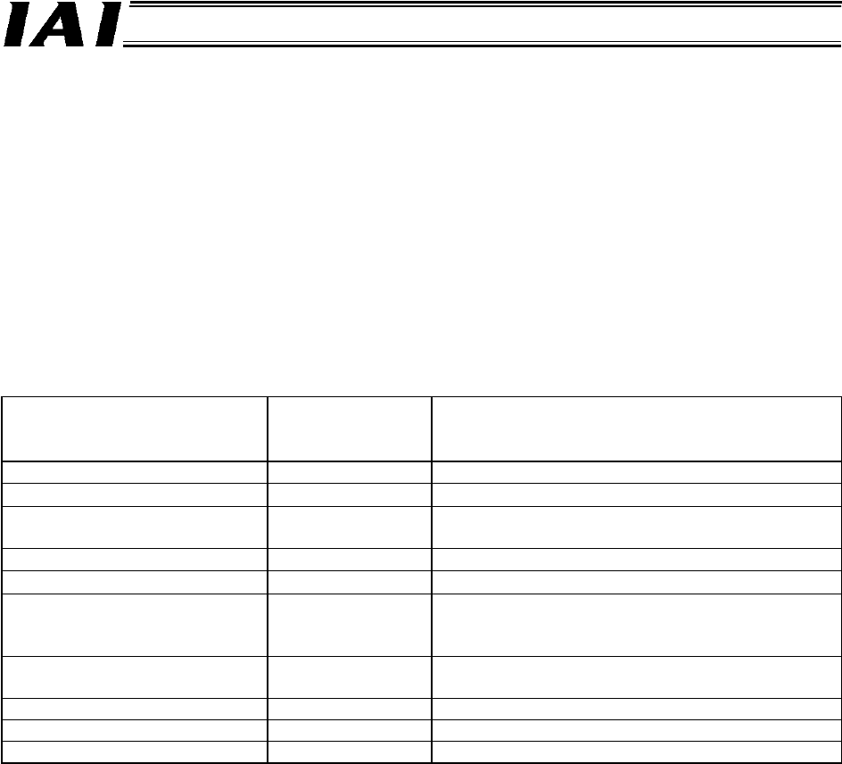
The key control functions available in this mode are listed below.
Key function
: Direct control
Δ: Indirect control
x: Disabled
Remarks
Home return operation
Positioning operation
Δ
A number in the position table is specified.
Speed and acceleration/
deceleration setting
Δ
Set in the position table.
Pitch (incremental) feed
Δ
Set in the position table.
Push-motion operation
Δ
Set in the position table.
Speed change during
movement
Δ
Two or more position numbers are combined.
(Refer to the operation manual for your
controller.)
Operation with acceleration
and deceleration set differently
Δ
Set in the position table.
Pause
Zone signal output
Each zone is set by parameters.
PIO pattern selection X *1
*1 The number of positions may be limited depending on the PIO pattern selected (via parameter No.
25) for each connected controller. Specify position numbers in compliance with the position
number limitation applicable to each controller. Normally, a maximum of 64 positions can be
specified.