
Manual


Table Of Contents
- 1. Overview
- 2. Specifications and Name of Each Part
- 2.1 General Specifications
- 2.2 External Dimensions
- 2.3 Name and Function of Each Part
- [1] Gateway status indicator LEDs
- [2] SIO communication status LEDs
- [3] Mode setting switch
- [4] External port switching input
- [5] Controller communication lines
- [6] DeviceNet communication connector
- [7] Baud-rate setting switches
- [8] Node-address setting switches
- [9] DeviceNet communication status LEDs
- [10] Port switch
- [11] Teaching pendant/PC connector
- [12] Power-supply input
- 3. Installation and Noise Elimination Measures
- 4. Wiring
- 4.1 Overall Configuration
- 4.2 I/O Signals of Gateway Unit
- 4.3 Design of SIO Communication Network (SIO Communication)
- 4.3.1 Wiring
- (1) Basics
- (2) Linking PCON/ACON/SCON controllers via SIO communication
- (3) Linking ERC2-SE controllers via SIO communication
- (4) Linking ERC2-NP/PN controllers via SIO communication
- (5) Wiring the emergency stop (EMG) circuit
- [1] Example of cutting off drive signals
- [2] Example of cutting off motor drive power
- 4.3.2 Axis Number Setting
- 4.3.1 Wiring
- 4.4 How to Connect Teaching Tools When Grounding the Positive Terminal of the 24-V Power Supply
- 5. Overview of DeviceNet
- 6. Address Configuration of Gateway Unit
- 7. Communication Signal Details
- 7.1 Overview of Communication Signal Timings
- 7.2 Communication Signals and Operation Timings
- (1) Controller ready (PWR)
- (2) Emergency stop (EMGS)
- (3) Alarm (ALM)
- (4) Reset (RES)
- (5) Pause (STP)
- (6) Moving (MOVE)
- (7) Servo ON command (SON)
- (8) Home return command (HOME)
- (9) Positioning start (CSTR)
- (10) Position complete (PEND)
- (11) Command position number (PC1 to PC512)
- (12) Completed position number (PM1 to PM256)
- (13) Zone (PZONE, ZONE1, ZONE2)
- (14) Jog + command/jog- command (JOG+/JOG-)
- (15) Jog/inching switching (JISL)
- (16) Teaching mode command (MOD)
- (17) Position data read command (PWRT)
- (18) Forced brake release (BKRL)
- 7.3 Basic Operation Timings
- 7.4 Command Transmission
- 8. Network System Building Procedure
- 8.1 Procedure
- 8.2 Settings for Controller Communication
- 8.3 Setting the Gateway Unit and PLC Master
- 8.4 Assigning the Master PLC Address by Free Assignment
- 8.5 Assigning the Master PLC Address by Fixed Assignment
- 9. Example of DeviceNet Operation
- 10. Troubleshooting
40
DeviceNet Gateway
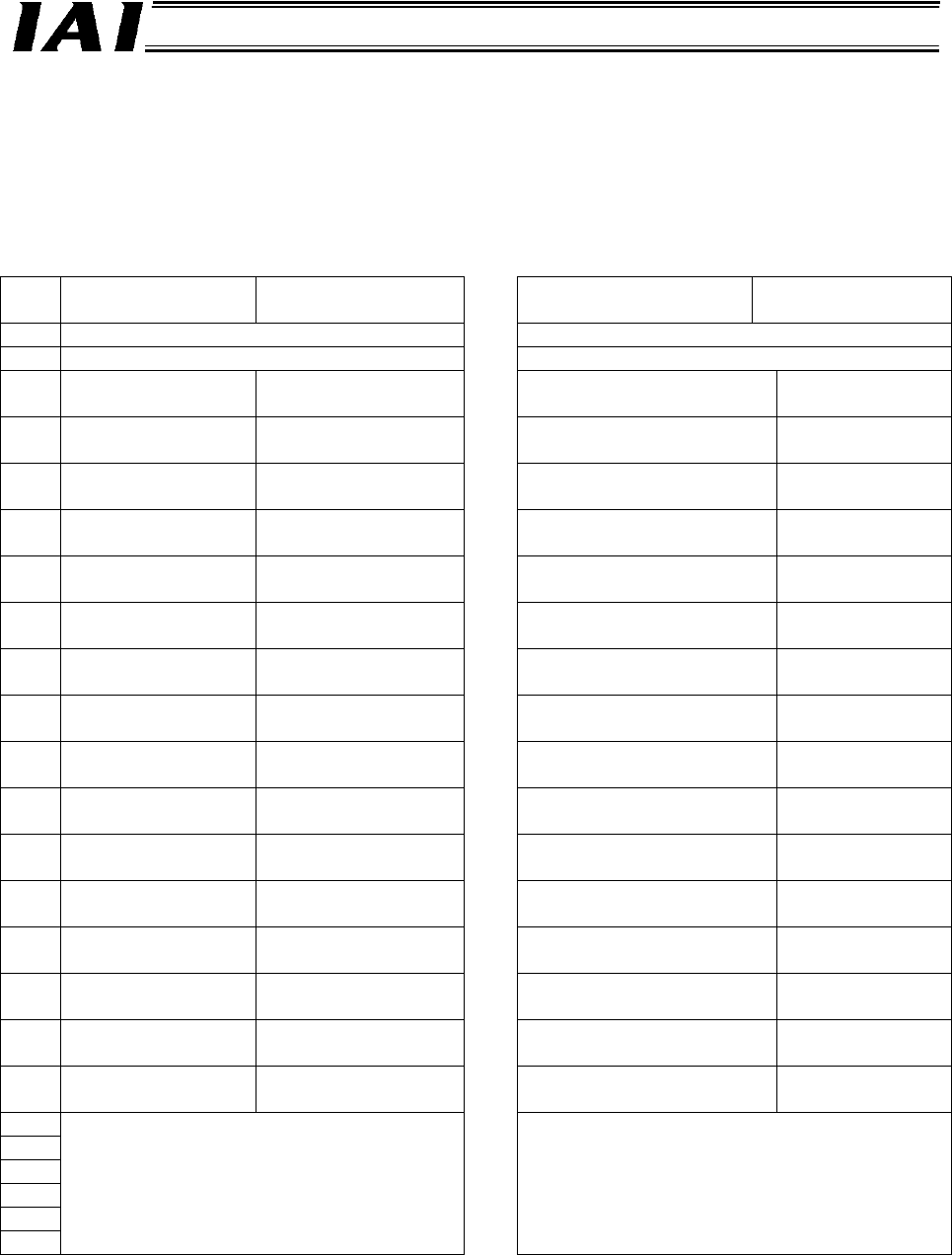
6.1.1 Overall Address Configuration
In the position number specification mode, the gateway control/status signal inputs and outputs use two
words each. With each axis, each control signal consists of one word in each PLC I/O area, and 24 input
words and 24 output words are occupied for the entire gateway unit.
The values in parentheses indicate axis numbers.
Output from PLC ⇒ Gateway Unit ⇒
Input to each axis
Node
address
Output from each axis ⇒ Gateway Unit ⇒
Input to PLC
CH+ b15
Upper
byte
b8 b7
Lower
byte
b0 b15
Upper
byte
b8 b7
Lower
byte
b0
+00 Gateway control signal 0 00 Gateway status signal 0
+01 Gateway control signal 1 01 Gateway status signal 1
+02
Command position
number (0)
Control signal (0) 02
Completed position
number + zone signal (0)
Status signal (0)
+03
Command position
number (1)
Control signal (1) 03
Completed position
number + zone signal (1)
Status signal (1)
+04
Command position
number (2)
Control signal (2) 04
Completed position
number + zone signal (2)
Status signal (2)
+05
Command position
number (3)
Control signal (3) 05
Completed position
number + zone signal (3)
Status signal (3)
+06
Command position
number (4)
Control signal (4) 06
Completed position
number + zone signal (4)
Status signal (4)
+07
Command position
number (5)
Control signal (5) 07
Completed position
number + zone signal (5)
Status signal (5)
+08
Command position
number (6)
Control signal (6) 08
Completed position
number + zone signal (6)
Status signal (6)
+09
Command position
number (7)
Control signal (7) 09
Completed position
number + zone signal (7)
Status signal (7)
+10
Command position
number (8)
Control signal (8) 10
Completed position
number + zone signal (8)
Status signal (8)
+11
Command position
number (9)
Control signal (9) 11
Completed position
number + zone signal (9)
Status signal (9)
+12
Command position
number (10)
Control signal (10) 12
Completed position
number + zone signal (10)
Status signal (10)
+13
Command position
number (11)
Control signal (11) 13
Completed position
number + zone signal (11)
Status signal (11)
+14
Command position
number (12)
Control signal (12) 14
Completed position
number + zone signal (12)
Status signal (12)
+15
Command position
number (13)
Control signal (13) 15
Completed position
number + zone signal (13)
Status signal (13)
+16
Command position
number (14)
Control signal (14) 16
Completed position
number + zone signal (14)
Status signal (14)
+17
Command position
number (15)
Control signal (15) 17
Completed position
number + zone signal (15)
Status signal (15)
+18 18
+19
+20
+21
+22
~
+23
Cannot be used.
23
Cannot be used.