
Manual


Table Of Contents
- 1. Overview
- 2. Specifications and Name of Each Part
- 2.1 General Specifications
- 2.2 External Dimensions
- 2.3 Name and Function of Each Part
- [1] Gateway status indicator LEDs
- [2] SIO communication status LEDs
- [3] Mode setting switch
- [4] External port switching input
- [5] Controller communication lines
- [6] DeviceNet communication connector
- [7] Baud-rate setting switches
- [8] Node-address setting switches
- [9] DeviceNet communication status LEDs
- [10] Port switch
- [11] Teaching pendant/PC connector
- [12] Power-supply input
- 3. Installation and Noise Elimination Measures
- 4. Wiring
- 4.1 Overall Configuration
- 4.2 I/O Signals of Gateway Unit
- 4.3 Design of SIO Communication Network (SIO Communication)
- 4.3.1 Wiring
- (1) Basics
- (2) Linking PCON/ACON/SCON controllers via SIO communication
- (3) Linking ERC2-SE controllers via SIO communication
- (4) Linking ERC2-NP/PN controllers via SIO communication
- (5) Wiring the emergency stop (EMG) circuit
- [1] Example of cutting off drive signals
- [2] Example of cutting off motor drive power
- 4.3.2 Axis Number Setting
- 4.3.1 Wiring
- 4.4 How to Connect Teaching Tools When Grounding the Positive Terminal of the 24-V Power Supply
- 5. Overview of DeviceNet
- 6. Address Configuration of Gateway Unit
- 7. Communication Signal Details
- 7.1 Overview of Communication Signal Timings
- 7.2 Communication Signals and Operation Timings
- (1) Controller ready (PWR)
- (2) Emergency stop (EMGS)
- (3) Alarm (ALM)
- (4) Reset (RES)
- (5) Pause (STP)
- (6) Moving (MOVE)
- (7) Servo ON command (SON)
- (8) Home return command (HOME)
- (9) Positioning start (CSTR)
- (10) Position complete (PEND)
- (11) Command position number (PC1 to PC512)
- (12) Completed position number (PM1 to PM256)
- (13) Zone (PZONE, ZONE1, ZONE2)
- (14) Jog + command/jog- command (JOG+/JOG-)
- (15) Jog/inching switching (JISL)
- (16) Teaching mode command (MOD)
- (17) Position data read command (PWRT)
- (18) Forced brake release (BKRL)
- 7.3 Basic Operation Timings
- 7.4 Command Transmission
- 8. Network System Building Procedure
- 8.1 Procedure
- 8.2 Settings for Controller Communication
- 8.3 Setting the Gateway Unit and PLC Master
- 8.4 Assigning the Master PLC Address by Free Assignment
- 8.5 Assigning the Master PLC Address by Fixed Assignment
- 9. Example of DeviceNet Operation
- 10. Troubleshooting
43
DeviceNet Gateway
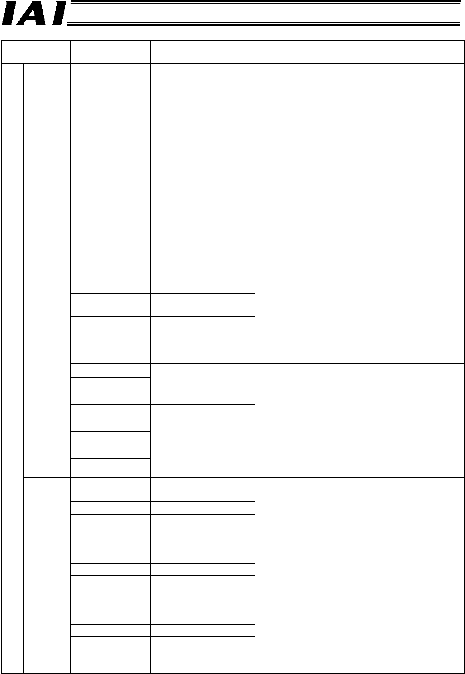
Signal type Bit
Signal
name
Description
15 RUN
Gateway Unit
normal output
This signal remains ON while the Gateway
Unit is operating normally.
The signal is synchronized with the
illumination of the LED (RUN) on the front
face of the unit.
14 G.ER
Gateway Unit
error detection output
This signal turns ON when a major shutdown
failure has been detected.
The signal is synchronized with the
illumination of the LED (G.ER) on the front
face of the unit.
13 T.ER
SIO communication
error detection output
This signal turns ON when a SIO link
communication error has been detected.
The signal is synchronized with the
illumination of the LED (T.ER) on the front
face of the unit.
12 TPC
Port switch ON output The status of the port switch on the front face
of the unit is output.
This signal is ON while the port switch is ON.
11 MOD4
Mode setting switch 4
output
10 MOD3
Mode setting switch 3
output
9 MOD2
Mode setting switch 2
output
8 MOD1
Mode setting switch 1
output
The setting status of each pin of the mode
setting switch is output.
This bit will turn ON (change to 1) when the
switch is turned ON.
7 Major V.4
6 Major V.2
5 Major V.1
The major version
number is output as a
three-bit binary value.
4 Minor V.16
3 Minor V.8
2 Minor V.4
1 Minor V.2
Status
signal 0
0 Minor V.1
The major version
number is output as a
five-bit binary value.
The Gateway version information is output.
You may need to check this information in
certain situations, such as when the Gateway
encountered a problem. Provide the
necessary wiring so that these signals can be
read by the PLC.
Example) If the version is 1.03, the major
version number is “1” (data: 001),
while the minor version number is
“3” (data: 00011).
15 LNK15 Linked Axis No. 15
14 LNK14 14
13 LNK13 13
12 LNK12 12
11 LNK11 11
10 LNK10 10
9 LNK9 9
8 LNK8 8
7 LNK7 7
6 LNK6 6
5 LNK5 5
4 LNK4 4
3 LNK3 3
2 LNK2 2
1 LNK1 1
PLC input
Status
signal 1
0 LNK0 0
Link connection of an axis selected for link
connection by any one of CFG15 to 0 will
become enabled when the MON signal is
turned ON. The signal corresponding to each
axis whose link connection is enabled turns
ON.