
Manual


Table Of Contents
- 1. Overview
- 2. Specifications and Name of Each Part
- 2.1 General Specifications
- 2.2 External Dimensions
- 2.3 Name and Function of Each Part
- [1] Gateway status indicator LEDs
- [2] SIO communication status LEDs
- [3] Mode setting switch
- [4] External port switching input
- [5] Controller communication lines
- [6] DeviceNet communication connector
- [7] Baud-rate setting switches
- [8] Node-address setting switches
- [9] DeviceNet communication status LEDs
- [10] Port switch
- [11] Teaching pendant/PC connector
- [12] Power-supply input
- 3. Installation and Noise Elimination Measures
- 4. Wiring
- 4.1 Overall Configuration
- 4.2 I/O Signals of Gateway Unit
- 4.3 Design of SIO Communication Network (SIO Communication)
- 4.3.1 Wiring
- (1) Basics
- (2) Linking PCON/ACON/SCON controllers via SIO communication
- (3) Linking ERC2-SE controllers via SIO communication
- (4) Linking ERC2-NP/PN controllers via SIO communication
- (5) Wiring the emergency stop (EMG) circuit
- [1] Example of cutting off drive signals
- [2] Example of cutting off motor drive power
- 4.3.2 Axis Number Setting
- 4.3.1 Wiring
- 4.4 How to Connect Teaching Tools When Grounding the Positive Terminal of the 24-V Power Supply
- 5. Overview of DeviceNet
- 6. Address Configuration of Gateway Unit
- 7. Communication Signal Details
- 7.1 Overview of Communication Signal Timings
- 7.2 Communication Signals and Operation Timings
- (1) Controller ready (PWR)
- (2) Emergency stop (EMGS)
- (3) Alarm (ALM)
- (4) Reset (RES)
- (5) Pause (STP)
- (6) Moving (MOVE)
- (7) Servo ON command (SON)
- (8) Home return command (HOME)
- (9) Positioning start (CSTR)
- (10) Position complete (PEND)
- (11) Command position number (PC1 to PC512)
- (12) Completed position number (PM1 to PM256)
- (13) Zone (PZONE, ZONE1, ZONE2)
- (14) Jog + command/jog- command (JOG+/JOG-)
- (15) Jog/inching switching (JISL)
- (16) Teaching mode command (MOD)
- (17) Position data read command (PWRT)
- (18) Forced brake release (BKRL)
- 7.3 Basic Operation Timings
- 7.4 Command Transmission
- 8. Network System Building Procedure
- 8.1 Procedure
- 8.2 Settings for Controller Communication
- 8.3 Setting the Gateway Unit and PLC Master
- 8.4 Assigning the Master PLC Address by Free Assignment
- 8.5 Assigning the Master PLC Address by Fixed Assignment
- 9. Example of DeviceNet Operation
- 10. Troubleshooting
45
DeviceNet Gateway
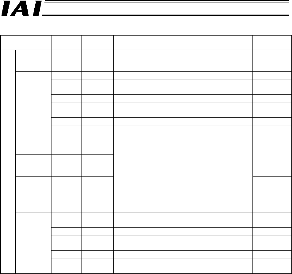
I/O Signal Details
Signal type Bit
Signal
name
Description Details
Command
position
number
Six-bit
data
(b13-8)
PC 32 to
PC1
Specify the command position number using a
binary value. *1
7.2 (11)
b7 - Cannot be used. -
b6 - Cannot be used. -
b5 - Cannot be used. -
b4 SON Servo on command 7.2 (7)
b3 STP Pause command 7.2 (5)
b2 HOME Home return command 7.2 (8)
b1 CSTR Start command 7.2 (9)
PLC output
Control
signal
b0 RES Reset command 7.2 (4)
Zone
signal
output 2
b15
ZONE2
*2
Zone
signal
output 1
b14 ZONE1
7.2 (13)
Completed
position
number
(alarm
output)
Six-bit
data
(b13-8)
PM32
to
PM1
The completed position number and zone signal
status are output. Read the completed position
number as a six-bit binary value.
If an alarm is present (= the ALM signal is ON), a
description of the alarm is output as the
completed position number.
(For the alarm descriptions to be output, refer to
the next table, “Alarm Description List.”
7.2 (12)
b7 EMGS Emergency stop 7.2 (2)
b6 - Cannot be used. -
b5 PWR Controller ready 7.2 (1)
b4 SV Ready (servo is on) 7.2 (7)
b3 MOVE Moving 7.2 (6)
b2 HEND Home return complete 7.2 (8)
b1 PEND Position complete 7.2 (10)
PLC input
Status
signal
b0 ALM Alarm 7.2 (3)
*1 The maximum number of positioning points is 16 under PIO control with ERC2-NP/PN controllers.
When the Gateway Unit is connected, however, up to 64 points can be specified.
*2 [ZONE 2] cannot be used with ERC2-NP/PN controllers.