
Manual


Table Of Contents
- 1. Overview
- 2. Specifications and Name of Each Part
- 2.1 General Specifications
- 2.2 External Dimensions
- 2.3 Name and Function of Each Part
- [1] Gateway status indicator LEDs
- [2] SIO communication status LEDs
- [3] Mode setting switch
- [4] External port switching input
- [5] Controller communication lines
- [6] DeviceNet communication connector
- [7] Baud-rate setting switches
- [8] Node-address setting switches
- [9] DeviceNet communication status LEDs
- [10] Port switch
- [11] Teaching pendant/PC connector
- [12] Power-supply input
- 3. Installation and Noise Elimination Measures
- 4. Wiring
- 4.1 Overall Configuration
- 4.2 I/O Signals of Gateway Unit
- 4.3 Design of SIO Communication Network (SIO Communication)
- 4.3.1 Wiring
- (1) Basics
- (2) Linking PCON/ACON/SCON controllers via SIO communication
- (3) Linking ERC2-SE controllers via SIO communication
- (4) Linking ERC2-NP/PN controllers via SIO communication
- (5) Wiring the emergency stop (EMG) circuit
- [1] Example of cutting off drive signals
- [2] Example of cutting off motor drive power
- 4.3.2 Axis Number Setting
- 4.3.1 Wiring
- 4.4 How to Connect Teaching Tools When Grounding the Positive Terminal of the 24-V Power Supply
- 5. Overview of DeviceNet
- 6. Address Configuration of Gateway Unit
- 7. Communication Signal Details
- 7.1 Overview of Communication Signal Timings
- 7.2 Communication Signals and Operation Timings
- (1) Controller ready (PWR)
- (2) Emergency stop (EMGS)
- (3) Alarm (ALM)
- (4) Reset (RES)
- (5) Pause (STP)
- (6) Moving (MOVE)
- (7) Servo ON command (SON)
- (8) Home return command (HOME)
- (9) Positioning start (CSTR)
- (10) Position complete (PEND)
- (11) Command position number (PC1 to PC512)
- (12) Completed position number (PM1 to PM256)
- (13) Zone (PZONE, ZONE1, ZONE2)
- (14) Jog + command/jog- command (JOG+/JOG-)
- (15) Jog/inching switching (JISL)
- (16) Teaching mode command (MOD)
- (17) Position data read command (PWRT)
- (18) Forced brake release (BKRL)
- 7.3 Basic Operation Timings
- 7.4 Command Transmission
- 8. Network System Building Procedure
- 8.1 Procedure
- 8.2 Settings for Controller Communication
- 8.3 Setting the Gateway Unit and PLC Master
- 8.4 Assigning the Master PLC Address by Free Assignment
- 8.5 Assigning the Master PLC Address by Fixed Assignment
- 9. Example of DeviceNet Operation
- 10. Troubleshooting
49
DeviceNet Gateway
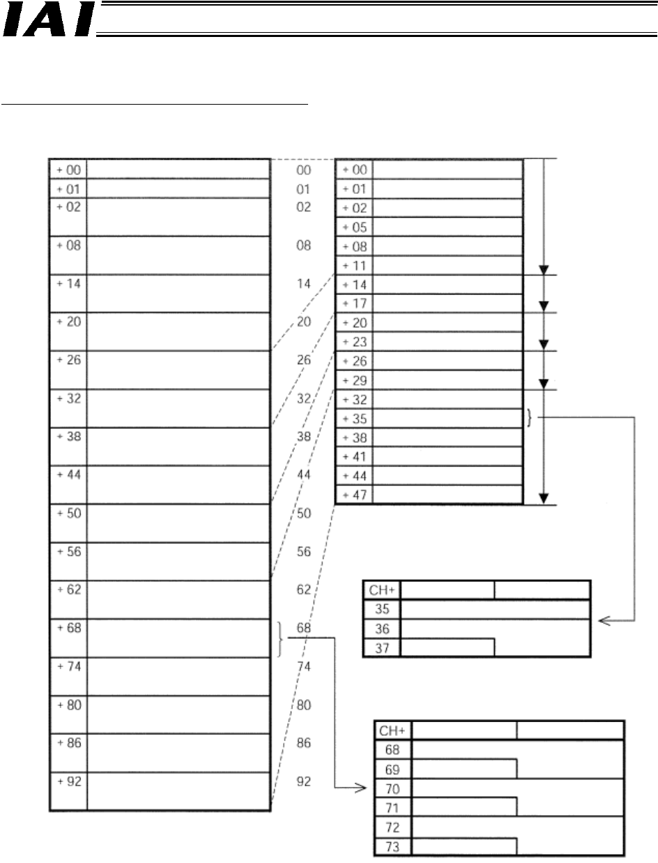
The overall address configuration is shown below.
“CH” indicates the head address of assigned areas in the DeviceNet master.
The values in parentheses indicate axis numbers.
(Note) If fixed assignment is sued, the
maximum number of assignable
channels is limited to 64.
Output from PLC ⇒ Gateway Unit
⇒ Input to each axis
Output from each axis ⇒ Gateway Unit
⇒ Input to PLC
CH+
CH+
Gateway control 0
Gateway control 1
Axis control (0)
Axis control (1)
Axis control (2)
Axis control (3)
Axis control (4)
Axis control (5)
Axis control (6)
Axis control (7)
Axis control (8)
Axis control (9)
Axis control (10)
Axis control (11)
Axis control (12)
Axis control (13)
Axis control (14)
Axis control (15)
Gateway status 0
Gateway status 1
Axis status (0)
Axis status (1)
Axis status (2)
Axis status (3)
Axis status (4)
Axis status (5)
Axis status (6)
Axis status (7)
Axis status (8)
Axis status (9)
Axis status (10)
Axis status (11)
Axis status (12)
Axis status (13)
Axis status (14)
Axis status (15)
Mode No. 1
Mode No. 2
Mode No. 3
Mode No. 4
Mode No. 5
Status signal (11
)
Current position data (11
)
Cannot be used.
Current-limiting value for
push motion (11)
b15 Upper byte b8
Speed (11)
Acceleration/deceleration
(11)
Positioning band (11)
Control signal (11)
Node
address
b15 U
pp
er b
y
te b8
b7 Lower byte b0
b7 Lower b
y
te b0
Position data specification (11)