
Manual


Table Of Contents
- 1. Overview
- 2. Specifications and Name of Each Part
- 2.1 General Specifications
- 2.2 External Dimensions
- 2.3 Name and Function of Each Part
- [1] Gateway status indicator LEDs
- [2] SIO communication status LEDs
- [3] Mode setting switch
- [4] External port switching input
- [5] Controller communication lines
- [6] DeviceNet communication connector
- [7] Baud-rate setting switches
- [8] Node-address setting switches
- [9] DeviceNet communication status LEDs
- [10] Port switch
- [11] Teaching pendant/PC connector
- [12] Power-supply input
- 3. Installation and Noise Elimination Measures
- 4. Wiring
- 4.1 Overall Configuration
- 4.2 I/O Signals of Gateway Unit
- 4.3 Design of SIO Communication Network (SIO Communication)
- 4.3.1 Wiring
- (1) Basics
- (2) Linking PCON/ACON/SCON controllers via SIO communication
- (3) Linking ERC2-SE controllers via SIO communication
- (4) Linking ERC2-NP/PN controllers via SIO communication
- (5) Wiring the emergency stop (EMG) circuit
- [1] Example of cutting off drive signals
- [2] Example of cutting off motor drive power
- 4.3.2 Axis Number Setting
- 4.3.1 Wiring
- 4.4 How to Connect Teaching Tools When Grounding the Positive Terminal of the 24-V Power Supply
- 5. Overview of DeviceNet
- 6. Address Configuration of Gateway Unit
- 7. Communication Signal Details
- 7.1 Overview of Communication Signal Timings
- 7.2 Communication Signals and Operation Timings
- (1) Controller ready (PWR)
- (2) Emergency stop (EMGS)
- (3) Alarm (ALM)
- (4) Reset (RES)
- (5) Pause (STP)
- (6) Moving (MOVE)
- (7) Servo ON command (SON)
- (8) Home return command (HOME)
- (9) Positioning start (CSTR)
- (10) Position complete (PEND)
- (11) Command position number (PC1 to PC512)
- (12) Completed position number (PM1 to PM256)
- (13) Zone (PZONE, ZONE1, ZONE2)
- (14) Jog + command/jog- command (JOG+/JOG-)
- (15) Jog/inching switching (JISL)
- (16) Teaching mode command (MOD)
- (17) Position data read command (PWRT)
- (18) Forced brake release (BKRL)
- 7.3 Basic Operation Timings
- 7.4 Command Transmission
- 8. Network System Building Procedure
- 8.1 Procedure
- 8.2 Settings for Controller Communication
- 8.3 Setting the Gateway Unit and PLC Master
- 8.4 Assigning the Master PLC Address by Free Assignment
- 8.5 Assigning the Master PLC Address by Fixed Assignment
- 9. Example of DeviceNet Operation
- 10. Troubleshooting
59
DeviceNet Gateway
6.3.1 Overall address configuration
Each Gateway control signal input or output consists of two words. Only in this mode, PPS0 to PPS2
and NPS0 to NPS4 of control word 0 are used to set the pattern and number of position-number
specification axes. This is followed by the command I/O areas each consisting of seven words, and
the Gateway control signal and command I/O areas each consisting of nine words. These areas are
fixed.
Although the control areas for each axis are assigned immediately after the fixed areas, positioner
operation axes should always be assigned first, followed by simple direct operation axes.
When assigning areas for each axis, make sure no empty bytes remain in between assigned bytes.
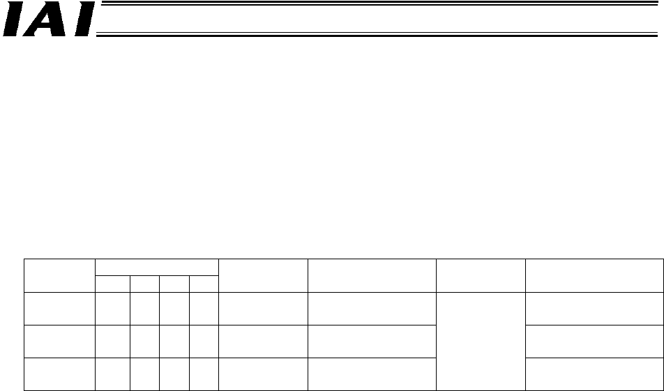
The total I/O area size of the Gateway varies according to how the mode setting switch SW1 is set,
as shown in the table below.
SW1
Mode
number
4 3 2 1
- Total I/O areas Fixed areas
Control areas for
each axis
7 X X X
{
Large mode
160 bytes = 80
words each
71 words each
8 X
{
X
{
Middle
mode
128 bytes = 64
words each
55 words each
9
{
X X
{
Small mode
64 bytes = 32
words each
9 words
each
23 words each
Up to 16 axes can be assigned, including positioner operation axes and simple direct operation axes,
within the areas specified in the table above.
With positioner operation axes, each axis control signal consists of one word for both input and
output. With simple direct operation axes, three PLC input signal words and four PLC output signal
words are available.
The following page provides an example, where three positioner operation axes and five simple direct
operation axes are assigned in the Small mode.