
Manual


Table Of Contents
- 1. Overview
- 2. Specifications and Name of Each Part
- 2.1 General Specifications
- 2.2 External Dimensions
- 2.3 Name and Function of Each Part
- [1] Gateway status indicator LEDs
- [2] SIO communication status LEDs
- [3] Mode setting switch
- [4] External port switching input
- [5] Controller communication lines
- [6] DeviceNet communication connector
- [7] Baud-rate setting switches
- [8] Node-address setting switches
- [9] DeviceNet communication status LEDs
- [10] Port switch
- [11] Teaching pendant/PC connector
- [12] Power-supply input
- 3. Installation and Noise Elimination Measures
- 4. Wiring
- 4.1 Overall Configuration
- 4.2 I/O Signals of Gateway Unit
- 4.3 Design of SIO Communication Network (SIO Communication)
- 4.3.1 Wiring
- (1) Basics
- (2) Linking PCON/ACON/SCON controllers via SIO communication
- (3) Linking ERC2-SE controllers via SIO communication
- (4) Linking ERC2-NP/PN controllers via SIO communication
- (5) Wiring the emergency stop (EMG) circuit
- [1] Example of cutting off drive signals
- [2] Example of cutting off motor drive power
- 4.3.2 Axis Number Setting
- 4.3.1 Wiring
- 4.4 How to Connect Teaching Tools When Grounding the Positive Terminal of the 24-V Power Supply
- 5. Overview of DeviceNet
- 6. Address Configuration of Gateway Unit
- 7. Communication Signal Details
- 7.1 Overview of Communication Signal Timings
- 7.2 Communication Signals and Operation Timings
- (1) Controller ready (PWR)
- (2) Emergency stop (EMGS)
- (3) Alarm (ALM)
- (4) Reset (RES)
- (5) Pause (STP)
- (6) Moving (MOVE)
- (7) Servo ON command (SON)
- (8) Home return command (HOME)
- (9) Positioning start (CSTR)
- (10) Position complete (PEND)
- (11) Command position number (PC1 to PC512)
- (12) Completed position number (PM1 to PM256)
- (13) Zone (PZONE, ZONE1, ZONE2)
- (14) Jog + command/jog- command (JOG+/JOG-)
- (15) Jog/inching switching (JISL)
- (16) Teaching mode command (MOD)
- (17) Position data read command (PWRT)
- (18) Forced brake release (BKRL)
- 7.3 Basic Operation Timings
- 7.4 Command Transmission
- 8. Network System Building Procedure
- 8.1 Procedure
- 8.2 Settings for Controller Communication
- 8.3 Setting the Gateway Unit and PLC Master
- 8.4 Assigning the Master PLC Address by Free Assignment
- 8.5 Assigning the Master PLC Address by Fixed Assignment
- 9. Example of DeviceNet Operation
- 10. Troubleshooting
62
DeviceNet Gateway
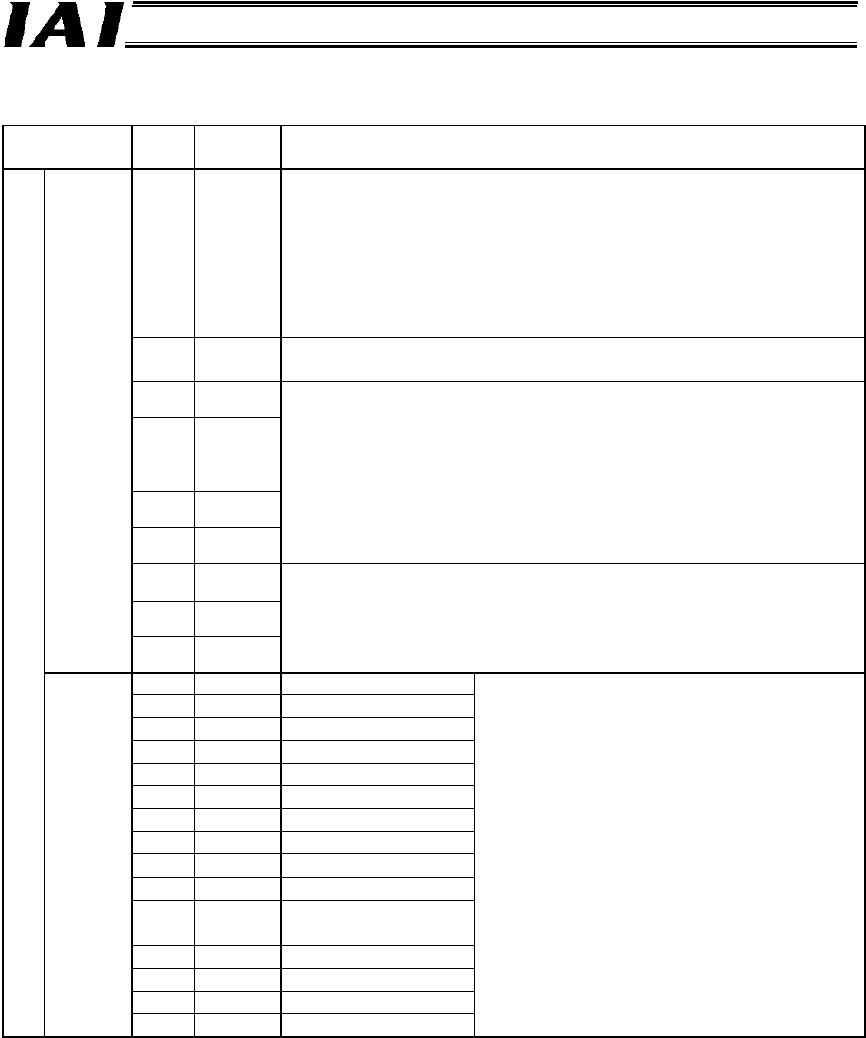
I/O Signal List
Signal type Bit
Signal
name
Description
15 MON
SIO link communication will start when this signal is turned ON, and
stop when it is turned OFF.
Do not turn the MON signal ON when CFG15 to 0 (linked axis
connection) are all OFF.
Also, do not turn all of CFG15 to 0 OFF when the MON signal is ON.
If CFG15 to 0 are all turned OFF and the MON signal turned ON, the
Gateway Unit will generate a SIO link error and the LED (T.ER) on the
front face of the unit will illuminate.
14-8 ---
These bits cannot be used.
Always set them to OFF (0).
7 NPS4
6 NPS3
5 NPS2
4 NPS1
3 NPS0
These bits are used in the command specification mode.
In any other mode, always set them to OFF (0).
Set the number of axes (0 to 16) used via positioner operation, using
a five-bit binary value. *1
2 PPS2
1 PPS1
Control
signal 0
0 PPS0
These bits are used in the command specification mode.
In any other mode, always set them to OFF (0).
Set the I/O pattern (pattern 0 to 5) of each axis to be used via
positioner operation, using a three-bit binary value. *2
15 CFG15 Link ON Axis No. 15
14 CFG14 14
13 CFG13 13
12 CFG12 12
11 CFG11 11
10 CFG10 10
9 CFG9 9
8 CFG8 8
7 CFG7 7
6 CFG6 6
5 CFG5 5
4 CFG4 4
3 CFG3 3
2 CFG2 2
1 CFG1 1
PLC output
Control
signal 1
0 CFG0 0
Specify the axis number corresponding to
each axis to be linked.
The axis will be connected when the signal is
turned ON (1), and disconnected when it is
turned OFF (0).
ON/OFF switching is permitted even when the
MON signal is ON.
(Cautions)
Do not turn ON the axis number signal
corresponding to any axis not physically
connected.
Do not turn ON any axis number signal
other than the specifiable number selected
by the mode setting switch.
If either of the above conditions is breached, a
SIO link error will occur.
*1 If the mode setting switch (SW1) is set to the command specification mode and the settings of NPS0 to
NPS4 indicate 0, all axes will become simple direct operation axes.
*2 Only one I/O pattern of 0 to 4 can be used for positioner operation axes.