
Manual


Table Of Contents
- 1. Overview
- 2. Specifications and Name of Each Part
- 2.1 General Specifications
- 2.2 External Dimensions
- 2.3 Name and Function of Each Part
- [1] Gateway status indicator LEDs
- [2] SIO communication status LEDs
- [3] Mode setting switch
- [4] External port switching input
- [5] Controller communication lines
- [6] DeviceNet communication connector
- [7] Baud-rate setting switches
- [8] Node-address setting switches
- [9] DeviceNet communication status LEDs
- [10] Port switch
- [11] Teaching pendant/PC connector
- [12] Power-supply input
- 3. Installation and Noise Elimination Measures
- 4. Wiring
- 4.1 Overall Configuration
- 4.2 I/O Signals of Gateway Unit
- 4.3 Design of SIO Communication Network (SIO Communication)
- 4.3.1 Wiring
- (1) Basics
- (2) Linking PCON/ACON/SCON controllers via SIO communication
- (3) Linking ERC2-SE controllers via SIO communication
- (4) Linking ERC2-NP/PN controllers via SIO communication
- (5) Wiring the emergency stop (EMG) circuit
- [1] Example of cutting off drive signals
- [2] Example of cutting off motor drive power
- 4.3.2 Axis Number Setting
- 4.3.1 Wiring
- 4.4 How to Connect Teaching Tools When Grounding the Positive Terminal of the 24-V Power Supply
- 5. Overview of DeviceNet
- 6. Address Configuration of Gateway Unit
- 7. Communication Signal Details
- 7.1 Overview of Communication Signal Timings
- 7.2 Communication Signals and Operation Timings
- (1) Controller ready (PWR)
- (2) Emergency stop (EMGS)
- (3) Alarm (ALM)
- (4) Reset (RES)
- (5) Pause (STP)
- (6) Moving (MOVE)
- (7) Servo ON command (SON)
- (8) Home return command (HOME)
- (9) Positioning start (CSTR)
- (10) Position complete (PEND)
- (11) Command position number (PC1 to PC512)
- (12) Completed position number (PM1 to PM256)
- (13) Zone (PZONE, ZONE1, ZONE2)
- (14) Jog + command/jog- command (JOG+/JOG-)
- (15) Jog/inching switching (JISL)
- (16) Teaching mode command (MOD)
- (17) Position data read command (PWRT)
- (18) Forced brake release (BKRL)
- 7.3 Basic Operation Timings
- 7.4 Command Transmission
- 8. Network System Building Procedure
- 8.1 Procedure
- 8.2 Settings for Controller Communication
- 8.3 Setting the Gateway Unit and PLC Master
- 8.4 Assigning the Master PLC Address by Free Assignment
- 8.5 Assigning the Master PLC Address by Fixed Assignment
- 9. Example of DeviceNet Operation
- 10. Troubleshooting
83
DeviceNet Gateway
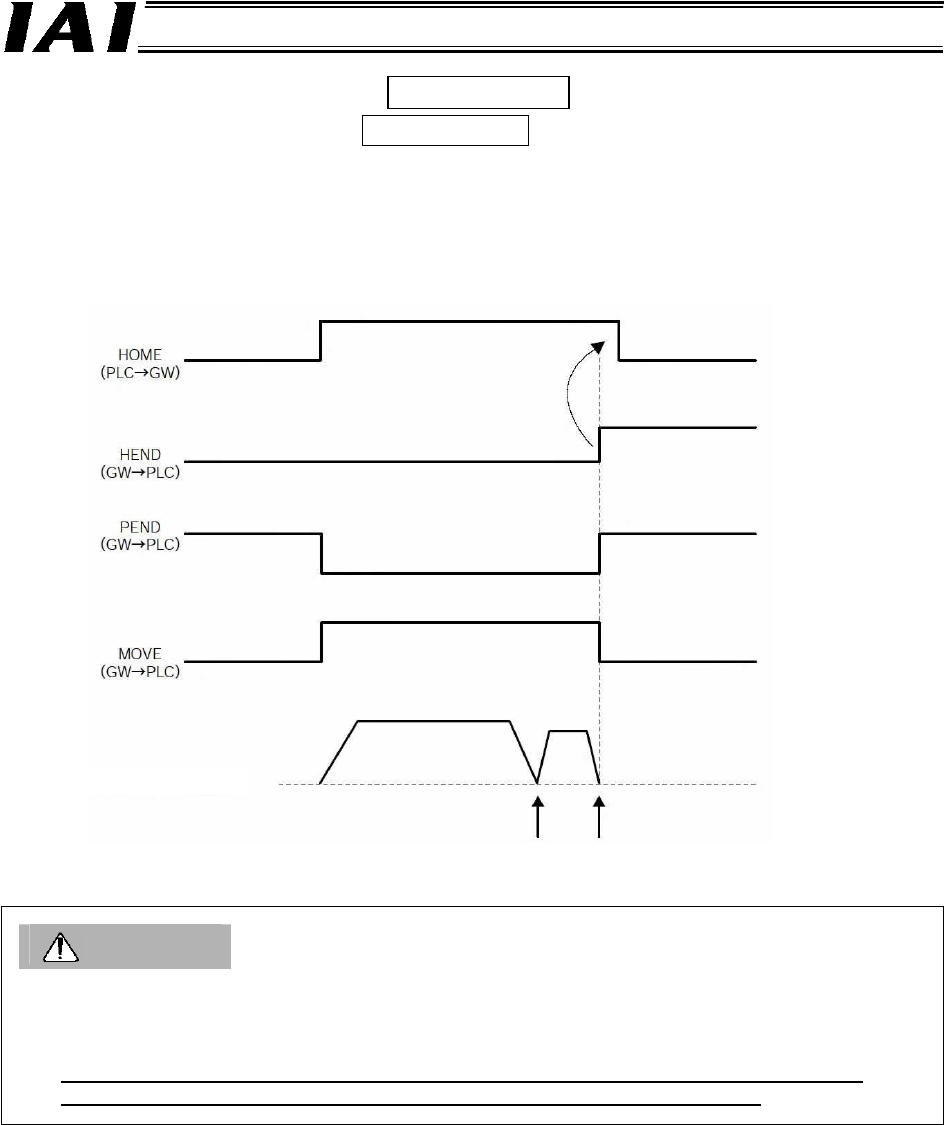
(8) Home return command (HOME)
Home return complete (HEND)
Home return operation is started at the leading edge of the HOME signal from “0” (OFF) to “1” (ON).
The HEND (home return complete) signal turns “1” (ON) when the home return is completed.
Turn the HOME signal “0” (OFF) after the HEND signal has turned “1” (ON). Once turned “1” (ON),
the HEND signal will not turn “0” (OFF) until the power is turned off or the HOME signal is input
again. This means that you can perform home return using the HOME signal as many times as
desired, even after the initial home return is completed.
Caution
1. With a positioner operation axis operated in the position number specification mode or command
specification mode, issuing a positioning command to a given position without performing home
return following the power on will cause the actuator to automatically return home and then
perform positioning, provided that it is the first positioning operation after the power on.
2. Take note that in any other mode, an alarm “Error code 83: ALARM HOME ABS (absolute
position movement command before completion of home return)” will generate.
PLC output signal
PLC input signal
A
ctuator operation
Mechanical end Stops at the home position.