
Manual


Table Of Contents
- 1. Overview
- 2. Specifications and Name of Each Part
- 2.1 General Specifications
- 2.2 External Dimensions
- 2.3 Name and Function of Each Part
- [1] Gateway status indicator LEDs
- [2] SIO communication status LEDs
- [3] Mode setting switch
- [4] External port switching input
- [5] Controller communication lines
- [6] DeviceNet communication connector
- [7] Baud-rate setting switches
- [8] Node-address setting switches
- [9] DeviceNet communication status LEDs
- [10] Port switch
- [11] Teaching pendant/PC connector
- [12] Power-supply input
- 3. Installation and Noise Elimination Measures
- 4. Wiring
- 4.1 Overall Configuration
- 4.2 I/O Signals of Gateway Unit
- 4.3 Design of SIO Communication Network (SIO Communication)
- 4.3.1 Wiring
- (1) Basics
- (2) Linking PCON/ACON/SCON controllers via SIO communication
- (3) Linking ERC2-SE controllers via SIO communication
- (4) Linking ERC2-NP/PN controllers via SIO communication
- (5) Wiring the emergency stop (EMG) circuit
- [1] Example of cutting off drive signals
- [2] Example of cutting off motor drive power
- 4.3.2 Axis Number Setting
- 4.3.1 Wiring
- 4.4 How to Connect Teaching Tools When Grounding the Positive Terminal of the 24-V Power Supply
- 5. Overview of DeviceNet
- 6. Address Configuration of Gateway Unit
- 7. Communication Signal Details
- 7.1 Overview of Communication Signal Timings
- 7.2 Communication Signals and Operation Timings
- (1) Controller ready (PWR)
- (2) Emergency stop (EMGS)
- (3) Alarm (ALM)
- (4) Reset (RES)
- (5) Pause (STP)
- (6) Moving (MOVE)
- (7) Servo ON command (SON)
- (8) Home return command (HOME)
- (9) Positioning start (CSTR)
- (10) Position complete (PEND)
- (11) Command position number (PC1 to PC512)
- (12) Completed position number (PM1 to PM256)
- (13) Zone (PZONE, ZONE1, ZONE2)
- (14) Jog + command/jog- command (JOG+/JOG-)
- (15) Jog/inching switching (JISL)
- (16) Teaching mode command (MOD)
- (17) Position data read command (PWRT)
- (18) Forced brake release (BKRL)
- 7.3 Basic Operation Timings
- 7.4 Command Transmission
- 8. Network System Building Procedure
- 8.1 Procedure
- 8.2 Settings for Controller Communication
- 8.3 Setting the Gateway Unit and PLC Master
- 8.4 Assigning the Master PLC Address by Free Assignment
- 8.5 Assigning the Master PLC Address by Fixed Assignment
- 9. Example of DeviceNet Operation
- 10. Troubleshooting
84
DeviceNet Gateway
(9) Positioning start (CSTR)
Upon detection of the leading edge of this signal from “0” (OFF) to “1” (ON), the target position
number corresponding to the binary code consisting of PC1 to PC322768 (The specific signals used
vary depending on the operation mode) will be read and the actuator will position itself to the target
position specified by the applicable position data. The same also applies when the position is
specified directly using a numerical value in the position data specification area.
Before executing this command, the target position, speed and other operation data must be set in
the position table using a PC/teaching pendant.
If this command is executed when no home return operation has been performed yet (= the HEND
output signal is “0” (OFF)) following the power on, the actuator will automatically perform the home
return operation and then position itself to the target position.
Turn this signal “0” (OFF) after confirming that the PEND signal has turned “0” (OFF).
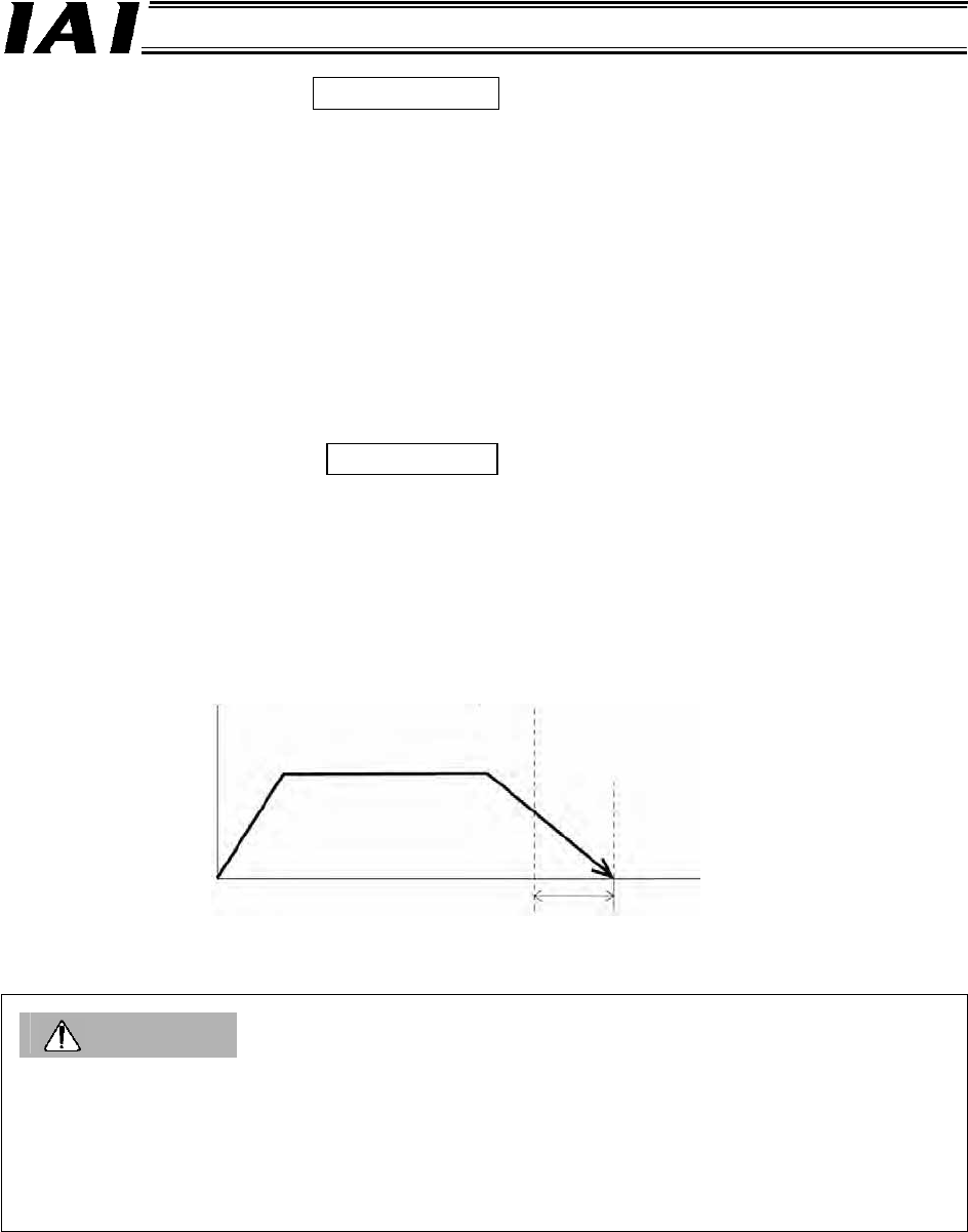
(10) Position complete (PEND)
This signal turns “1” (ON) when the actuator has moved to the target position and entered the
positioning band, or push-motion operation has completed (the actuator has not missed the work).
If the servo turns ON, the applicable position is defined as the target position and thus this signal
turns “1” (ON). It will turn “0” (OFF) when the positioning operation is subsequently started via the
HOME signal or CSTR signal.
Caution
If the servo turns OFF or an emergency stop is actuated while the actuator is stopped at the target
position, the PEND signal turns “0” (OFF).
When the servo subsequently turns ON, the PEND signal will turn “1” (ON) again if the actuator is
inside the positioning band. If CSTR remains “1” (ON), the PEND signal does not become “1” (ON)
even when the current actuator position is inside the positioning band. The PEND signal will become
“1” (ON) after the CSTR signal turns “0” (OFF).
Speed
The position complete
signal turns ON here.
Target position
Travel distance
Positioning band
Time
PLC output signal
PLC input signal