
Manual


Table Of Contents
- 1. Overview
- 2. Specifications and Name of Each Part
- 2.1 General Specifications
- 2.2 External Dimensions
- 2.3 Name and Function of Each Part
- [1] Gateway status indicator LEDs
- [2] SIO communication status LEDs
- [3] Mode setting switch
- [4] External port switching input
- [5] Controller communication lines
- [6] DeviceNet communication connector
- [7] Baud-rate setting switches
- [8] Node-address setting switches
- [9] DeviceNet communication status LEDs
- [10] Port switch
- [11] Teaching pendant/PC connector
- [12] Power-supply input
- 3. Installation and Noise Elimination Measures
- 4. Wiring
- 4.1 Overall Configuration
- 4.2 I/O Signals of Gateway Unit
- 4.3 Design of SIO Communication Network (SIO Communication)
- 4.3.1 Wiring
- (1) Basics
- (2) Linking PCON/ACON/SCON controllers via SIO communication
- (3) Linking ERC2-SE controllers via SIO communication
- (4) Linking ERC2-NP/PN controllers via SIO communication
- (5) Wiring the emergency stop (EMG) circuit
- [1] Example of cutting off drive signals
- [2] Example of cutting off motor drive power
- 4.3.2 Axis Number Setting
- 4.3.1 Wiring
- 4.4 How to Connect Teaching Tools When Grounding the Positive Terminal of the 24-V Power Supply
- 5. Overview of DeviceNet
- 6. Address Configuration of Gateway Unit
- 7. Communication Signal Details
- 7.1 Overview of Communication Signal Timings
- 7.2 Communication Signals and Operation Timings
- (1) Controller ready (PWR)
- (2) Emergency stop (EMGS)
- (3) Alarm (ALM)
- (4) Reset (RES)
- (5) Pause (STP)
- (6) Moving (MOVE)
- (7) Servo ON command (SON)
- (8) Home return command (HOME)
- (9) Positioning start (CSTR)
- (10) Position complete (PEND)
- (11) Command position number (PC1 to PC512)
- (12) Completed position number (PM1 to PM256)
- (13) Zone (PZONE, ZONE1, ZONE2)
- (14) Jog + command/jog- command (JOG+/JOG-)
- (15) Jog/inching switching (JISL)
- (16) Teaching mode command (MOD)
- (17) Position data read command (PWRT)
- (18) Forced brake release (BKRL)
- 7.3 Basic Operation Timings
- 7.4 Command Transmission
- 8. Network System Building Procedure
- 8.1 Procedure
- 8.2 Settings for Controller Communication
- 8.3 Setting the Gateway Unit and PLC Master
- 8.4 Assigning the Master PLC Address by Free Assignment
- 8.5 Assigning the Master PLC Address by Fixed Assignment
- 9. Example of DeviceNet Operation
- 10. Troubleshooting
88
DeviceNet Gateway
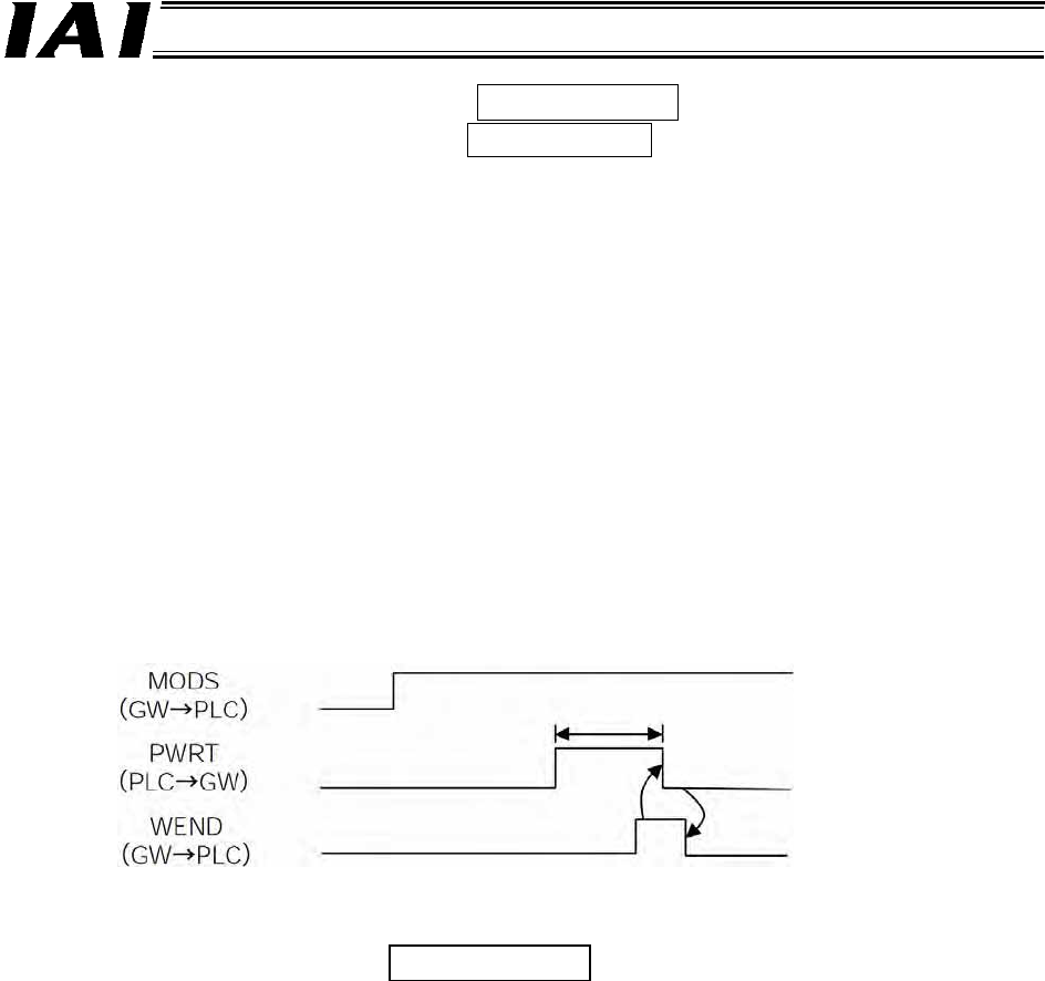
(17) Position data read command (PWRT)
Position data read complete (WEND)
These signals are used when the actuator is operated in PIO pattern 1 (teaching mode) as a
positioner operation axis in the command specification mode.
The PWRT signal is effective when the MODS signal is “1” (ON).
Turn the PWRT signal “1” (ON) and keep it in this condition for 20 msec or more (*1), and the current
position data will be written to the “Position” field under the position number currently specified by the
PLC. (*2)
The WEND signal turns “1” (ON) upon completion of writing.
On the host PLC side, the PWRT signal should be turned “0” (OFF) after the WEND signal has
turned “1” (ON).
If the PWRT signal is turned “0” (OFF) before the WEND signal turns “1” (ON), the WEND signal will
not turn “1” (ON).
Turning the PWRT signal “0” (OFF) will turn the WEND signal “0” (OFF).
*1 Keep the signal “1” (ON) for 20 msec or more. If the signal is turned “1” (ON) for less than 20
msec, the data may not be written.
*2 If any data other than the position is undefined, the default value of the corresponding
parameter will be written.
(18) Forced brake release (BKRL)
The brake can be forcibly released by turning this signal “1” (ON).
PLC input signal
PLC output signal
20 msec or more
PLC output signal