
Manual


Table Of Contents
- 1. Overview
- 2. Specifications and Name of Each Part
- 2.1 General Specifications
- 2.2 External Dimensions
- 2.3 Name and Function of Each Part
- [1] Gateway status indicator LEDs
- [2] SIO communication status LEDs
- [3] Mode setting switch
- [4] External port switching input
- [5] Controller communication lines
- [6] DeviceNet communication connector
- [7] Baud-rate setting switches
- [8] Node-address setting switches
- [9] DeviceNet communication status LEDs
- [10] Port switch
- [11] Teaching pendant/PC connector
- [12] Power-supply input
- 3. Installation and Noise Elimination Measures
- 4. Wiring
- 4.1 Overall Configuration
- 4.2 I/O Signals of Gateway Unit
- 4.3 Design of SIO Communication Network (SIO Communication)
- 4.3.1 Wiring
- (1) Basics
- (2) Linking PCON/ACON/SCON controllers via SIO communication
- (3) Linking ERC2-SE controllers via SIO communication
- (4) Linking ERC2-NP/PN controllers via SIO communication
- (5) Wiring the emergency stop (EMG) circuit
- [1] Example of cutting off drive signals
- [2] Example of cutting off motor drive power
- 4.3.2 Axis Number Setting
- 4.3.1 Wiring
- 4.4 How to Connect Teaching Tools When Grounding the Positive Terminal of the 24-V Power Supply
- 5. Overview of DeviceNet
- 6. Address Configuration of Gateway Unit
- 7. Communication Signal Details
- 7.1 Overview of Communication Signal Timings
- 7.2 Communication Signals and Operation Timings
- (1) Controller ready (PWR)
- (2) Emergency stop (EMGS)
- (3) Alarm (ALM)
- (4) Reset (RES)
- (5) Pause (STP)
- (6) Moving (MOVE)
- (7) Servo ON command (SON)
- (8) Home return command (HOME)
- (9) Positioning start (CSTR)
- (10) Position complete (PEND)
- (11) Command position number (PC1 to PC512)
- (12) Completed position number (PM1 to PM256)
- (13) Zone (PZONE, ZONE1, ZONE2)
- (14) Jog + command/jog- command (JOG+/JOG-)
- (15) Jog/inching switching (JISL)
- (16) Teaching mode command (MOD)
- (17) Position data read command (PWRT)
- (18) Forced brake release (BKRL)
- 7.3 Basic Operation Timings
- 7.4 Command Transmission
- 8. Network System Building Procedure
- 8.1 Procedure
- 8.2 Settings for Controller Communication
- 8.3 Setting the Gateway Unit and PLC Master
- 8.4 Assigning the Master PLC Address by Free Assignment
- 8.5 Assigning the Master PLC Address by Fixed Assignment
- 9. Example of DeviceNet Operation
- 10. Troubleshooting
89
DeviceNet Gateway
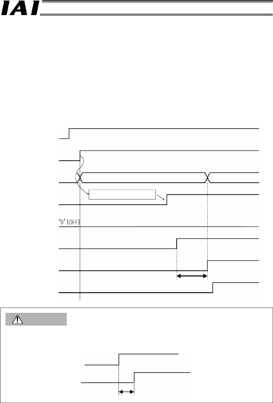
7.3 Basic Operation Timings
(1) Ready
Start the actuator by following the procedure below after confirming that the slider or rod is not
colliding with a mechanical end and the load is not contacting any surrounding equipment:
[1] Cancel the emergency stop or enable energization of the motor drive power.
[2] Supply the 24-VDC controller power: 24-V and 0-V terminals on the power-supply terminal
block
[3] Set the minimum required parameters.
(Example)
• To change the feed rate during teaching:
Change the value of parameter No. 35 (Safety speed).
[4] In the positioner mode or simple direct mode, set optimal values in the “Position,” “Speed,”
“Acceleration,” “Deceleration” and other fields in the position table.
Caution
When the power is turned on while an emergency stop is being actuated and then the emergency stop
is cancelled (= the SON signal is turned “1” (ON)), the servo will turn ON after an elapse of up to 1.6
sec following the cancellation of the emergency stop.
Condition of
safet
y
circuit
Emergency stop cancelled
Controller power
Su
pp
l
y
of 24 VDC
SV lamp
(
Front
p
anel
)
Controller read
y
(
CRDY
)
Pause (STP)
Servo ON command
(SON)
Position complete
(PEND)
Operation ready
(SV)
Illuminates in orange only for 2 seconds, and then turns off.
Default parameter setting
Green
Pause cancelled
1.6 sec or less
Emergency stop cancelled
1.6 sec or less
Servo ON