
Manual


Table Of Contents
- 1. Overview
- 2. Specifications and Name of Each Part
- 2.1 General Specifications
- 2.2 External Dimensions
- 2.3 Name and Function of Each Part
- [1] Gateway status indicator LEDs
- [2] SIO communication status LEDs
- [3] Mode setting switch
- [4] External port switching input
- [5] Controller communication lines
- [6] DeviceNet communication connector
- [7] Baud-rate setting switches
- [8] Node-address setting switches
- [9] DeviceNet communication status LEDs
- [10] Port switch
- [11] Teaching pendant/PC connector
- [12] Power-supply input
- 3. Installation and Noise Elimination Measures
- 4. Wiring
- 4.1 Overall Configuration
- 4.2 I/O Signals of Gateway Unit
- 4.3 Design of SIO Communication Network (SIO Communication)
- 4.3.1 Wiring
- (1) Basics
- (2) Linking PCON/ACON/SCON controllers via SIO communication
- (3) Linking ERC2-SE controllers via SIO communication
- (4) Linking ERC2-NP/PN controllers via SIO communication
- (5) Wiring the emergency stop (EMG) circuit
- [1] Example of cutting off drive signals
- [2] Example of cutting off motor drive power
- 4.3.2 Axis Number Setting
- 4.3.1 Wiring
- 4.4 How to Connect Teaching Tools When Grounding the Positive Terminal of the 24-V Power Supply
- 5. Overview of DeviceNet
- 6. Address Configuration of Gateway Unit
- 7. Communication Signal Details
- 7.1 Overview of Communication Signal Timings
- 7.2 Communication Signals and Operation Timings
- (1) Controller ready (PWR)
- (2) Emergency stop (EMGS)
- (3) Alarm (ALM)
- (4) Reset (RES)
- (5) Pause (STP)
- (6) Moving (MOVE)
- (7) Servo ON command (SON)
- (8) Home return command (HOME)
- (9) Positioning start (CSTR)
- (10) Position complete (PEND)
- (11) Command position number (PC1 to PC512)
- (12) Completed position number (PM1 to PM256)
- (13) Zone (PZONE, ZONE1, ZONE2)
- (14) Jog + command/jog- command (JOG+/JOG-)
- (15) Jog/inching switching (JISL)
- (16) Teaching mode command (MOD)
- (17) Position data read command (PWRT)
- (18) Forced brake release (BKRL)
- 7.3 Basic Operation Timings
- 7.4 Command Transmission
- 8. Network System Building Procedure
- 8.1 Procedure
- 8.2 Settings for Controller Communication
- 8.3 Setting the Gateway Unit and PLC Master
- 8.4 Assigning the Master PLC Address by Free Assignment
- 8.5 Assigning the Master PLC Address by Fixed Assignment
- 9. Example of DeviceNet Operation
- 10. Troubleshooting
92
DeviceNet Gateway
(3) Operation by position number specification
The following explains positioner operation in the position number specification mode or command
specification mode.
Operation
Enter position data in the controller’s position table beforehand, and specify each desired position
number using the applicable link resister in the PLC.
Push-motion operation, speed change during movement, pitch feed by relative coordinate
specification and other operations are the same as the corresponding operations performed in the
PIO (I/O cable) mode. Refer to the operation manuals for the PCON, ACON, SCON and ERC2.
[1] Set the position number in the command position number register.
[2] Next, confirm that the position complete (PEND) signal is “1” (ON) and then turn the start
command (CSTR) signal “1” (ON).
[3] PEND turns “0” (OFF) tdpf after CSTR has turned “1” (ON).
[4] Turn CSTR “0” (OFF) after confirming that PEND has turned “0” (OFF).
[5] MOVE turns “1” (ON) simultaneously as PEND turns “0” (OFF) or within 1 Mt thereafter.
[6] When the remaining travel falls within the specified positioning band (INP), PEND turns “1”
(ON) if CSTR is “0” (OFF), after which the completed position number is output.
Accordingly, when reading the completed position number after completion of positioning,
check the position number after waiting for an appropriate time after PEND has turned “1”
(ON) (= time needed to complete the remaining travel).
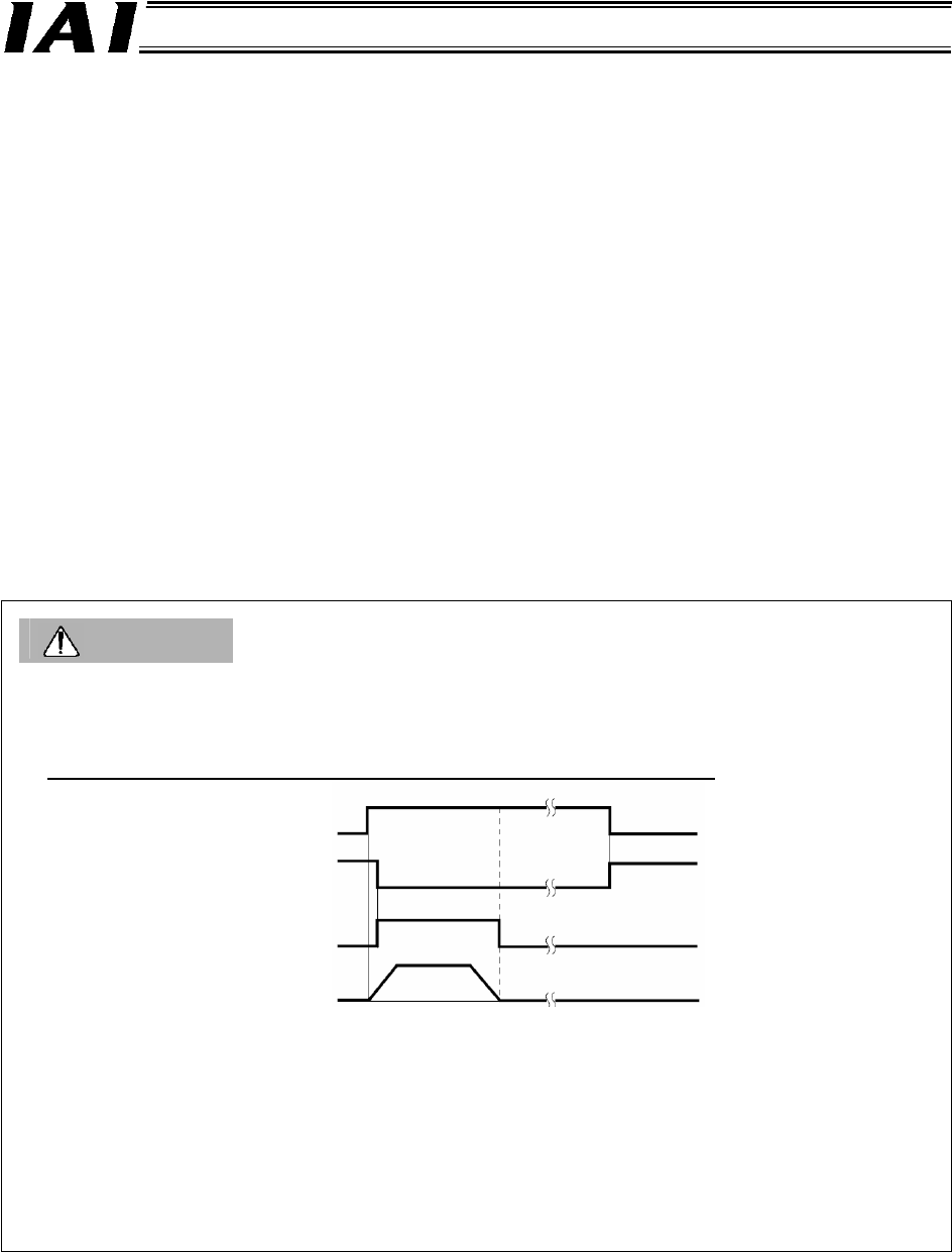
Caution
• When the start (CSTR) signal turns “1” (ON), the position complete (PEND) signal turns “0” (OFF)
and moving (MOVE) signal turns “1” (ON).
Be sure to turn the CSTR signal OFF after conforming that PEND has turned OFF while the CSTR
signal is still ON.
If CSTR remains ON, PEND will not turn ON after completion of movement
, as shown below.
• If another movement command specifying the same position is issued, the position complete
output will turn OFF, but the moving output will not turn ON.
• The moment the position complete output turns ON while the moving output is ON, the moving
output turns OFF even when the actuator is moving. Accordingly, increasing the positioning band
among position data may result in a situation where the actuator is still moving after the moving
output has turned OFF simultaneously as the turning ON of the position complete output.
• When the actuator reaches a soft limit after continuous incremental moves, the position complete
signal is output.
Start (CSTR)
Position complete (PEND)
Moving (MOVE)
Actuator
Movement complete