ProfiBus Gateway Unit RCM-GW-PR Operation Manual, Second Edition
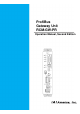
CAUTION Note on Connecting a PC or Teaching Pendant to the Gateway Unit Grounded via the Positive Terminal of Its 24-V Power Supply If the positive terminal of the gateway unit’s 24-V power supply is grounded, use a SIO converter as shown below to connect a teaching pendant or PC to the gateway unit. In this case, do not connect the FG of the SIO converter. Teaching pendant PC, etc.
CAUTION If the positive terminal of the gateway unit’s 24-V power supply is grounded, the gateway unit cannot be connected directly to a teaching pendant or PC. If a teaching pendant or PC is connected directly to the gateway unit grounded in this condition, the power-supply circuit may be shorted and the PC/teaching pendant may be damaged. Gateway unit Cannot be connected directly. This teaching pendant cannot be used this way.
PfofiBus Gateway Table of Contents 1. Overview ................................................................................................................... 1 1.1 1.2 1.3 1.4 ProfiBus Gateway Unit ................................................................................................................ 1 What Is ProfiBus? ........................................................................................................................ 2 Application Example of Gateway Unit ...............
PfofiBus Gateway 6.4 Command Transmission............................................................................................................ 95 7. Building Your Network System ................................................................................ 96 7.1 7.2 7.3 7.4 Procedure .................................................................................................................................. 96 Setting the Controller ..........................................................
PfofiBus Gateway 1. Overview 1.1 ProfiBus Gateway Unit The ProfiBus Gateway Unit (hereinafter referred to as “ProfiBus Gateway” or “Gateway Unit”) is used to connect a ProfiBus communication protocol network on which a host programmable controller (hereinafter “PLC”) operates, to a SIO communication sub-network (Modbus communication protocol) linking ROBO Cylinder controllers.
PfofiBus Gateway 1.2 What Is ProfiBus? (1) FA communication system In FA communication, each communication specification varies depending on the communicating equipment, type of information, and purpose of communication, among others. In general, however, the FA communication system is divided into the information level, controller level and field level, as shown below.
PfofiBus Gateway (5) ProfiBus ProfiBus is an open field network most commonly used in the world today. It was first established under DIN 19245 (German standard) in Germany in 1989, and standardized under EN 50170 (European standard) in July 1996. In January 2000, ProfiBus became an international standard under IEC 61158. There are two ProfiBus protocols designed for different purposes: ProfiBus-DP for factory automation (FA), and ProfiBus-PA for process automation. This manual covers ProfiBus-DP.
PfofiBus Gateway 1.4 Features and Key Functions 1.4.1 Features The ProfiBus gateway unit lets you select a desired operation mode from three modes including the position number specification mode, direct numerical specification mode and command specification mode. (1) Position number specification mode In this mode, a desired position number is specified to operate the actuator. Up to 16 axes can be connected. The position data, speed, acceleration/deceleration, etc.
Key function Command Operation by position data specification Direct specification of speed and acceleration/deceleration Direct specification of positioning band Push-motion operation Operation by position number specification Position table enabling Maximum number of storable position numbers Reading of completed position number Selection of controller PIO pattern Zone (parameter) Position zone (P table) Reading of various status signals Speed change during movement Operation at different acceleration a
PfofiBus Gateway Next, the relationship of the number of positions supported by each controller under each PIO pattern, and the maximum number of positions that can be stored in the gateway unit, is explained. Take note that the number of positions may become subject to restrictions. PIO pattern (Parameter No.
PfofiBus Gateway 1.5 Description of Model Name Base model ProfiBus specification Gateway Unit 1.
PfofiBus Gateway 2. Specifications and Name of Each Part 2.
PfofiBus Gateway (Installed dimension) 2.
PfofiBus Gateway 2.3 Name and Function of Each Part [1] Gateway Status LEDs RUN: Normal G.ER: Error C.ER: ProfiBus controller error T.
PfofiBus Gateway [1] Gateway status LEDs Indicated status RUN Steady green Unlit G.ER C.ER Steady red Unlit Steady red T.ER Blinking red Unlit Steady red Blinking red Unlit Description The Gateway CPU is operating. CPU operation is stopped. If this LED does not come on after turning on the power, the Gateway is experiencing a CPU error. The Gateway is experiencing a CPU error or major shutdown failure. Normal state.
PfofiBus Gateway [3] Mode setting switch This switch is used to set the operation mode of the ProfiBus gateway. Before operating this switch, turn off the ProfiBus gateway power. If any position between No. 1 and No. 5 is selected, the position table settings of the controller will become invalid. SW1 turns ON when tilted to the right. {: ON X: OFF SW1 No.
PfofiBus Gateway [6] ProfiBus communication connector This connector is used to connect the ProfiBus communication lines. D-sub, 9-pin connector (female) ProfiBus communication connector Pin No. Signal name 1 NC 2 NC 3 B-Line 4 RTS 5 GND 6 +5V 7 NC 8 A-Line 9 NC Housing Shield Description Not connected Not connected Communication line B (RS485) Request to send Signal ground (insulated) +5-V output (insulated) Not connected Communication line A (RS485) Not connected Cable shield Connected to the frame.
PfofiBus Gateway [9] ProfiBus status LEDs The three LEDs of (LINE-) ON, LINE-OFF and ERR on the front face of the board indicate the node status and network status. (The remaining LED is not used.) These LEDs illuminate in one of two colors (red or green), and each LED indicates a different monitored status, as shown in the table below.
PfofiBus Gateway [10] Port switch This switch is used to enable the teaching pendant/PC connector (TP) (PORT ON = Start communication). Set this switch to the OFF position when connecting/removing the communication cable connector for teaching pendant or PC software. To use the teaching pendant or PC software, plug in the connector first, and then set the switch to the OFF position. (Also check the signal status of the port switching input [4].
PfofiBus Gateway 3. Installation and Noise Elimination Measures Exercise due caution regarding the installation environment. 3.1 Installation Environment. a. b. c. d. e. The Gateway Unit is not dustproof or waterproof (oilproof). Accordingly, avoid using the Gateway Unit in a dusty place or place where the unit may come in contact with oil mist or splashed cutting fluid. Prevent the Gateway Unit from receiving direct sunlight or irradiated heat from large heat sources such as heat treatment ovens.
PfofiBus Gateway b. Notes on wiring method Separate the communication lines of the Gateway Unit and ProfiBus module from lines carrying large current such as power circuits. (Do not bundle them together or place them in the same cable duct.) c. Noise sources and elimination of noise There are many noise sources, but the ones you should pay most attention to when building your system are solenoid valves, magnet switches and relays. Noise from these sources can be eliminated using the following measures.
PfofiBus Gateway 3.4 Installation Examine appropriate settings for the control box size, installation position of the Gateway Unit and cooling method of the control box, so that the temperature around the Gateway Unit will remain at or below 40°C. Install the Gateway Unit vertically on a wall, as shown below, and provide a minimum clearance of 50 mm above and below the unit, with a minimum clearance of 100 mm provided on all sides for wiring access.
24-V power supply Teaching pendant Gateway Unit Host system (PLC master) SIO communication network Terminal resistor Controller link cable 4-way junction PfofiBus Gateway 4. Wiring 4.1 Overall Configuration The following is an example of ProfiBus system configuration using the Gateway Unit.
PfofiBus Gateway The ProfiBus network is wired as shown below. For details on ProfiBus-DP, check the operation manual for the master (PLC) or website of the Japanese PROFIBUS Organization. Master (Node address 2) Terminal resistor Terminal resistor Slave Slave Slave Slave (Node address 3) (Node address 4) (Node address 5) (Node address 6) [1] [2] [3] [4] A device connected to a network and assigned an address is called a “node.” A node may be a master or slave.
PfofiBus Gateway [6] The ProfiBus gateway connector should be the D-sub, 9-pin (female) connector recommended by the ProfiBus DP Standard under EN 50170, as shown below. The network connectors are not supplied. Pin No.
PfofiBus Gateway 4.2 I/O Signals of Gateway Unit (1) Connection diagram Gateway Unit ProfiBus communication cable Teaching pendant/ PC connector Teaching pendant Emergency stop Emergency stop signal output for teaching pendant Allowable load voltage: 30 VDC Allowable load current: 1 A Gateway power supply 24 VDC ±10%, 300 mA max.
PfofiBus Gateway (2) Port control and emergency stop signal output The teaching pendant/PC connector port can be operated by external signals, other than by ON/OFF switching of the port switch on the Gateway Unit. While the port is ON, the Gateway Unit outputs contact signals of the emergency stop pushbutton switch on the teaching pendant. Therefore, you can design an emergency stop circuit or other protective circuit for the entire system by incorporating these signals.
SIO communication Power-supply connector input connector 24 V N S1 S2 PORT IN PORT N SDA SDB GND FG ProfiBus communication connector B-Line *1 RTS GND +5V A-Line Description Positive side of the 24-VDC Gateway power supply Negative side of the 24-VDC Gateway power supply Teaching-pendant emergency stop signal output External port switching input SIO communication line A SIO communication line B Ground Frame ground Communication line B (RS485) Request to send Signal ground (insulated) +5-V output (insu
PfofiBus Gateway 4.3 Design of SIO Communication Network (SIO Communication) 4.3.1 Wiring (1) Basics Item Number of connected units Communication cable length Communication cable Terminal resistor Description 16 axes max. (The specific number varies depending on the operation mode. Refer to 1.4, “Features of Gateway Unit.”) Total cable length: 100 m max. Double shielded twisted-pair cable (AWG22) Recommended cable: HK-SB/20276 X L 2P X AWG22 by Taiyo Electric Wire & Cable 220 Ω 1/4 W Caution 1.
PfofiBus Gateway a. Detail connection diagram Details of SIO link connection are illustrated below. Controller link cables are available as options, but the customer must provide the communication trunk.
PfofiBus Gateway c. Controller link cable (CB-RCB-CTL002) This is an optional cable for the controller. You must purchase this cable separately. Controller end e-CON connector 3-1473562-4 (Housing color: Orange) Mini DIN connector Signal Yellow Orange Signal Blue The following parts are supplied with the controller link cable. [1] 4-way junction Model: 5-1473574-4 [2] e-CON connector 4-1473562-4 Outer diameter of applicable wire [3] Terminal resistor 220 Ω 1/4 W by AMP x 1 unit by AMP x 1 unit 1.
PfofiBus Gateway (3) SIO communication connection for ERC2-SE For details, refer to the ERC2-SE operation manual. Use 4-way junctions to connect the cables as shown below. The power-supply & I/O cable and network connection cable (including the 4-way junction and eCON connector) are standard accessories of the ERC2-SE.
PfofiBus Gateway (4) SIO communication connection for ERC2-NP/PN Use relay terminal blocks to connect the cables as shown below.
PfofiBus Gateway (5) Wiring the emergency stop (EMG) circuit When designing an emergency stop circuit that incorporates the emergency stop switch on the teaching pendant connected to the Gateway Unit, emergency stop signals output from the “S1” and “S2” terminals of the Gateway Unit can be used. This way, all connected ROBO Cylinder controllers can be stopped instantly in case of emergency by operating the emergency stop switch on the teaching pendant connected to the Gateway Unit. Caution 1.
PfofiBus Gateway [1] Example of cutting off drive signals Teaching pendant Emergency stop button Gateway Unit TP connector Emergency stop Emergency reset switch stop button PCON, ACON controller SIO connector SIO communication Connection SIO detection connector signal (H) connection detection circuit Gateway power supply Port switch EMG signal detection (H) 24-VDC input power supply (2 A max.
PfofiBus Gateway [2] Example of cutting off motor drive power Teaching pendant Emergency stop button Gateway Unit TP connector Emergency stop Emergency reset switch stop button SIO connector PCON, ACON controller SIO communication Connection SIO detection connector signal (H) connection detection circuit Gateway power supply Port switch EMG signal detection (H) 24-VDC input power supply (2 A max.
PfofiBus Gateway 4.3.2 Axis Number Setting The following explanation applies to PCON, ACON and ERC2 controllers. Set an axis number as a SIO-linked slave station number. The axis number of axis 1 is “0,” while that of axis 16 is “F.” Set an appropriate axis number using a hexadecimal value between 0 and F. Axis numbers can be set on the teaching pendant or in the PC software.
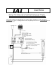
PfofiBus Gateway 4.4 How to Connect the Teaching Tool When the Positive Terminal of the 24-V Power Supply Is Grounded If the positive terminal of the 24-V power supply is grounded (= +24 V is grounded), use a SIO converter as shown below to connect a teaching pendant or PC to the gateway unit. In this case, do not connect the FG of the SIO converter. Teaching pendant PC, etc. Do not allow the FG of the PC to be connected to ground.
PfofiBus Gateway 5. Address Configuration of Gateway Unit All data exchanged between the master station and the controller are tentatively stored in the internal memory of the Gateway Unit, and then transmitted cyclically. Accordingly, the PLC program recognizes these data as remote ProfiBus I/Os. Up to 16 ROBO Cylinder controllers can be connected to the Gateway Unit, with the connected controllers assigned an axis number of 0 to 15, respectively.
PfofiBus Gateway 5.1.1 Overall address configuration In the position number specification mode, four bytes are used by the gateway control signals, and also by the status signals, to be input/output. For each axis, each control signal occupies two bytes in the PLC I/O area, and a total of 48 bytes are occupied by signal inputs, and also by signal outputs, for the entire gateway unit. The values in parentheses ( ) indicate axis numbers.
PfofiBus Gateway 5.1.2 Gateway Control/Status Signals The initial fixed area in the address configuration is used by signals that control the gateway unit, and consists of four input bytes and four output bytes. These signals are used to control the ON/OFF of SIO communication and monitor the SIO communication status and gateway unit status.
PfofiBus Gateway I/O Signal List Signal type Byte Signal name Description 7 MON SIO link communication will start when this signal is turned ON, and stop when it is turned OFF. Do not turn the MON signal ON when CFG15 to 0 (linked axis connection) are all OFF. Also, do not turn all of CFG15 to 0 OFF when the MON signal is ON. If CFG15 to 0 are all turned OFF and the MON signal turned ON, the Gateway Unit will generate a SIO link error and the LED (T.ER) on the front face of the unit will illuminate.
PfofiBus Gateway Signal type Byte Bit Signal name 7 RUN Gateway Unit normal output 6 G.ER Gateway Unit error detection output 5 T.ER SIO-link communication error detection output 4 TPC Port switch ON output +0 Status signal 0 3 2 1 PLC input 0 +1 +2 Status signal 1 +3 Description 7 6 5 4 3 2 1 0 7 6 5 4 3 2 1 0 7 6 5 4 3 2 1 0 Mode setting switch 4 ON output Mode setting switch 3 MOD3 ON output Mode setting switch 2 MOD2 ON output Mode setting switch 1 MOD1 ON output Major V.
PfofiBus Gateway 5.1.3 Assignment for Each Axis The input signal and output signal of each axis consist of two bytes each in the PLC I/O area. Control signals and status signals are ON/OFF signals defined in units of bits. The command position number or completed position number is handled as a 1-byte (8-bit) binary data. Specify each command position number within the range of position numbers set by the controller of each axis.
PfofiBus Gateway I/O Signal Details PLC output Signal type Control signal Command position number PLC input *2 Signal name b7 - Cannot be used. - b6 - Cannot be used. - b5 - Cannot be used. - b4 SON Servo on command 6.2 (7) b3 STP Pause command 6.2 (5) b2 HOME Home return command 6.2 (8) b1 CSTR Start command 6.2 (9) b0 RES Reset command 6.2 (4) 6-bit data (b5-0) RC 32 ~ PC1 Specify the command position number using a binary value.*1 6.
PfofiBus Gateway [Alarm List] The table below summarizes the content of each alarm that may be output by PM8 to PM1 (as a binary code) while the alarm is present. For details on each alarm, refer to the operation manual for the controller.
PfofiBus Gateway 5.2 Direct Numerical Specification Mode In the direct numerical specification mode, the position data, speed, acceleration/deceleration, positioning band (push band) and push-current limiting value are specified directly as numerical values to operate the actuator. One of five patters can be set according to the maximum number of connected axes. (Mode setting switch SW1) Also, the current position data can be read at any time. The position table need not be set for each axis.
PfofiBus Gateway 5.2.1 Overall Address Configuration Four bytes are used by the gateway control signals, and also by the status signals, to be input/output. In the direct numerical specification mode, the control signals of each axis consist of 12 bytes in the PLC output area (gateway input area) and six bytes in the PLC input area (gateway output area). The number of controlled axes is set by the mode setting switch (SW1), and the applicable data areas vary depending on the setting of this switch.
PfofiBus Gateway The overall address configuration is shown below. The byte address indicates the initial address of the assigned area in the master. The values in parentheses ( ) indicate axis numbers.
PfofiBus Gateway 5.2.2 Gateway Control/Status Signals The initial fixed area in the address configuration is used by signals that control the gateway unit, and consists of four input bytes and four output bytes. These signals are used to control the ON/OFF of SIO communication and monitor the SIO communication status and gateway unit status.
PfofiBus Gateway I/O Signal List Signal type Byte Signal name Description 7 MON SIO link communication will start when this signal is turned ON, and stop when it is turned OFF. Do not turn the MON signal ON when CFG15 to 0 (linked axis connection) are all OFF. Also, do not turn all of CFG15 to 0 OFF when the MON signal is ON. If CFG15 to 0 are all turned OFF and the MON signal turned ON, the Gateway Unit will generate a SIO link error and the LED (T.ER) on the front face of the unit will illuminate.
PfofiBus Gateway Signal type Byte Bit Signal name 7 RUN Gateway Unit normal output 6 G.ER Gateway Unit error detection output 5 T.ER SIO-link communication error detection output 4 TPC Port switch ON output +0 Status signal 0 3 2 1 PLC input 0 +1 +2 Status signal 1 +3 48 Description 7 6 5 4 3 2 1 0 7 6 5 4 3 2 1 0 7 6 5 4 3 2 1 0 Mode setting switch 4 ON output Mode setting switch 3 MOD3 ON output Mode setting switch 2 MOD2 ON output Mode setting switch 1 MOD1 ON output Major V.
PfofiBus Gateway 5.2.3 Assignment for each axis Control and status signals are set using ON (1)/OFF (0) signal bits, while current-limiting value for push-mode operation and acceleration/deceleration are set using one-byte (eight-bit) hexadecimal data. Speed, target position data, in-position band and current position data are three-byte (24-bit) hexadecimal data. It is recommended that control and status signals be transferred to, and used in, bit registers.
PfofiBus Gateway PLC input = Axis status signal Byte address Status signal Sign (Sign) Current position data (signed 24-bit integer) * “Byte+” indicates the Gateway head address, while n indicates an axis number (0 to 15). Caution 1. Signed 24-bit hexadecimal data output or input from/to the PLC is treated as a negative value when the most significant bit is “1.” Take note that all these data are treated as normal numerical data within the PLC.
PfofiBus Gateway I/O Signal Details Signal type Bit Signal name 24-bit data - Currentlimiting value for push motion 8-bit data - PLC output Target position data Speed 24-bit data - Acceleration/ deceleration 8-bit data - Description Details 6.3 (4) Set a signed 24-bit integer (unit: 0.01 mm) based on hexadecimal notation. Example) To specify +25.4 mm, set “0009ECH” (“2540” in decimal notation). z The maximum value that can be set is +9999.99 mm = 999999 (decimal) = 0F423FH (hexadecimal).
PfofiBus Gateway Signal type PLC output In-position band Control signal PLC input Status signal 52 Bit Signal name Description Details 24-bit data - 6.3 (4) Set a 24-bit integer (unit: 0.01 mm) based on hexadecimal notation. Example) To specify +25.4 mm, set “0009ECH” (“2540” in decimal notation). (Notes) z Set position data within the soft stroke limits. z Specify the direction of push-motion operation using DIR. z Even if in-position band is not set, the setting of parameter No.
PfofiBus Gateway 5.3 Command Specification Mode In this operation mode, one of two patterns can be combined including one (simple direct operation) where only the target position data is specified as a numerical value and all other position data are specified via a position number to operate the actuator, and the other (positioner operation) where the actuator is operated only by specifying a position number.
PfofiBus Gateway For all items, the top row indicates positioner operation, while the bottom row indicates simple direct operation. {: Direct control Key function Remarks ∆: Indirect control X: Disabled { Home return operation { Positioning operation Specify the position table number. *1 ∆ Specify all positioning data other than the position in the position table, and specify the {∆ position data and position table number at the same time. Speed/acceleration setting Set in the position table.
PfofiBus Gateway 5.3.1 Overall Address Configuration Input/output Gateway control signals consist of four bytes each. Only in this mode, PPS0 to PPS2 and NPS0 to NPS4 of control signal 0 are used to set the pattern and number of position-number specification axes. The subsequent 14 bytes constitute the command input/output area, and a total of 18 bytes each for input and output, including the Gateway control signals and command area, constitute the fixed area.
PfofiBus Gateway Example of Address Configuration Output from PLC ⇒ Gateway Unit ⇒ Input to each axis Byte address Gateway control area Command I/O area 2 bytes 8 bytes Upper byte Lower byte Gateway control signal 0 Gateway control signal 1 Request command Data 0 Data 1 Output from each axis ⇒ Gateway Unit ⇒ Input to PLC Upper byte Lower byte Gateway status signal 0 Gateway status signal 1 Response command Data 0 Data 2 Data 1 Data 2 Data 3 Data 4 Data 5 Data 3 Data 4 Data 5 Positioner opera
PfofiBus Gateway 5.3.2 Gateway Control/Status Signals The initial fixed area in the address configuration is used by signals that control the gateway unit, and consists of four input bytes and four output bytes. These signals are used to control the ON/OFF of SIO communication and monitor the SIO communication status and gateway unit status.
PfofiBus Gateway I/O Signal List Signal type Byte Signal name Description 7 MON SIO link communication will start when this signal is turned ON, and stop when it is turned OFF. Do not turn the MON signal ON when CFG15 to 0 (linked axis connection) are all OFF. Also, do not turn all of CFG15 to 0 OFF when the MON signal is ON. If CFG15 to 0 are all turned OFF and the MON signal turned ON, the Gateway Unit will generate a SIO link error and the LED (T.ER) on the front face of the unit will illuminate.
PfofiBus Gateway Signal type Byte Bit Signal name 7 RUN Gateway Unit normal output 6 G.ER Gateway Unit error detection output 5 T.ER SIO-link communication error detection output 4 TPC Port switch ON output +0 Status signal 0 3 2 1 PLC input 0 +1 +2 Status signal 1 +3 Description 7 6 5 4 3 2 1 0 7 6 5 4 3 2 1 0 7 6 5 4 3 2 1 0 Mode setting switch 4 ON output Mode setting switch 3 MOD3 ON output Mode setting switch 2 MOD2 ON output Mode setting switch 1 MOD1 ON output Major V.
PfofiBus Gateway 5.3.3 Assignment for Each Axis The I/O signals of each axis vary in terms of the size and content of each applicable area depending on whether the axis is a positioner operation axis or simple direct operation axis. (1) Control/status signals for positioner operation axis Each axis consists of two PLC output (control signal) bytes and two PLC input (status signal) bytes, as shown below. Five patterns are available depending on the PIO pattern set by the gateway control signal PPS.
PfofiBus Gateway I/O Signal Details Signal type Signal name Pattern No.
PfofiBus Gateway (2) Control/status signals for simple direct operation axis Each axis consists of eight PLC output (control signal) bytes and six PLC input (status signal) bytes, as shown below. The position data specification and current position data signals use singed 32-bit hexadecimals based on integers that are multiples of 0.01 mm.
PfofiBus Gateway I/O Signal Details PLC output Signal type Signal name Description Details Set a signed 32-bit integer (unit: 0.01 mm) based on hexadecimal notation. Example) To specify +25.4 mm, set “0009ECH” (“2540” in decimal notation). z The maximum value that can be set is +9999.99 6.3 (5) mm = 999999 (decimal) = 0F423FH (hexadecimal). z A negative value is indicated by a 2’s complement, which means that the most significant bit becomes “1.” z Set position data within the soft stroke limits.
PfofiBus Gateway Caution The corresponding “default parameter value” will not be applied to any movement data that must be specified directly as a numerical value from the PLC. Accordingly, take note that the actuator will not operate or an alarm will generate when any such movement data is not specified as a numerical value. The table below summarizes the method for specifying movement data in each operation mode.
PfofiBus Gateway 5.3.4 Command Area In the command specification mode, command areas are provided to let you use the various commands explained below to read/write the position table, among others. (1) Address configuration The request command area and response command area consist of 14 bytes each in the range of (Byte+ 04) to (Byte+ 17).
PfofiBus Gateway (2) Command list The available commands and commands are listed below. Function category Handshake Position table data write Position table data read Writing of position table data to ROM Present alarm code read Current value monitor Code 0000H 1000H 1001H 1002H 1003H 1004H 1005H 1006H 1007H 1008H 1040H 1041H 1042H 1043H 1044H 1045H 1046H 1047H 1048H 0DA0H 02E0H 0342H Description Clear a request command. Write a target position. Write an in-position band. Write a speed.
PfofiBus Gateway (3) Each command and data format [1] Position table data write commands Command name Byte+*1 PLC output (request) Target position write +4 1000H 6 Position number 8 Position data *2 10 12 Axis number 0 to FH *3 14 (RSV) 16 (RSV) In-position write +4 1001H 6 Position number 8 In-position band data *4 10 12 Axis number 0 to FH *3 14 (RSV) 16 (RSV) Speed write +4 1002H 6 Position number 8 Speed data *4 10 12 Axis number 0 to FH *3 14 (RSV) 16 (RSV) Each zone positive +4 1003H boundary write
PfofiBus Gateway Command name Deceleration write Push motion currentlimiting value write Byte+*1 +4 6 8 10 12 14 16 +4 6 8 Load current threshold write 10 12 14 16 +4 6 8 10 12 14 16 *1 *2 *3 *4 *5 *6 68 PLC output (request) 1006H Position number Deceleration data *5 0 Axis number 0 to FH *3 (RSV) (RSV) 1007H Position number 0000 to 00FFH (00FFH: maximum current) 0 Axis number 0 to FH *3 (RSV) (RSV) 1008H Position number 0000 to 00FFH (00FFH: maximum current) 0 Axis number 0 to FH *3 (RSV) (RSV) PL
PfofiBus Gateway [2] Position table data read commands Command name Byte+*1 PLC output (request) Target position read +4 1040H 6 Position number 8 0 10 0 12 Axis number 0 to FH *2 14 (RSV) 16 (RSV) In-position band read +4 1041H 6 Position number 8 0 10 0 12 Axis number 0 to FH *2 14 (RSV) 16 (RSV) Speed read +4 1042H 6 Position number 8 0 10 0 12 Axis number 0 to FH *2 14 (RSV) 16 (RSV) Each zone positive +4 1043H boundary read 6 Position number 8 0 10 0 12 Axis number 0 to FH *2 14 (RSV) 16 (RSV) Each z
PfofiBus Gateway Command name Deceleration read Current-limiting value read *6 Load current threshold read *1 *2 *3 *4 *5 *6 70 Byte+*1 +4 6 8 10 12 14 16 +4 6 PLC output (request) 1046H Position number 0 0 Axis number 0 to FH *2 (RSV) (RSV) 1047H Position number 8 0 10 12 14 16 +4 6 0 Axis number 0 to FH *2 (RSV) (RSV) 1048H Position number 8 0 10 12 14 16 0 Axis number 0 to FH *2 (RSV) (RSV) PLC input (response) Same as the value in the request command if normal.
PfofiBus Gateway [3] Position table data ROM write command Command name Byte+*1 PLC output (request) +4 0DA0H Position table data ROM writing coil write 6 0 8 0 10 0 12 Axis number 0 to FH *2 14 (RSV) 16 (RSV) +4 02E0H Position table data ROM writing complete 6 0 coil read 8 0 *1 *2 PLC input (response) Same as the value in the request command if normal. Same as the value in the request command if normal.
PfofiBus Gateway [5] Current position read command Command name Byte+*1 PLC output (request) +2 0440H Monitor the current position of a specified 3 0 axis. 4 0 5 0 *1 *2 *3 72 PLC input (response) Same as the value in the request command if normal. Current position of the specified axis*3 (32-bit signed integer) 6 Axis number 0 to FH *2 7 (RSV) 8 (RSV) Relative byte address recognized with respect to the Gateway head address Data 00 to 0FH correspond to axis numbers (0) to (15), respectively.
PfofiBus Gateway [6] Group specification broadcast command The axes specified by the group number are started simultaneously to the position specified by the position number. When this command is issued, the Gateway and each controller communicate in the broadcast mode, meaning that the controller does not return any response.
PfofiBus Gateway (4) Error response If a command error occurs, the most significant bit (b7) of the response command will turn ON. In addition, one of the following error codes will be set in response data 1. If no link is currently formed, nothing will be shown in the response command.
PfofiBus Gateway 6 Communication Signal Details 6.1 Overview of Communication Signal Timings When a given control signal is turned ON to operate the ROBO Cylinder using the sequence program in the PLC, the maximum response time before a response (status) signal will be received is expressed by the formula below: Maximum response time (msec) = Yt + Xt + 2 x Mt + Command processing time (operation time, etc.
PfofiBus Gateway 76
PfofiBus Gateway 6.2 Communication Signals and Operation Timings (1) Controller ready (PWR) PLC input signal This signal turns “1” (ON) when the controller becomes ready following the power on. Function This signal turns “1” (ON) when the controller has been initialized properly following the power on and becomes ready, regardless of the alarm condition, servo status, etc. Even when an alarm is present, the PWR signal still turns “1” (ON) as long as the controller becomes ready.
PfofiBus Gateway (5) Pause (STP) PLC output signal Turning this signal “1” (ON) causes the axis to stop temporarily (decelerate to a stop). Turning it “0” (OFF) resumes the axis movement. The relationship of the STP signal and MOVE (moving) signal is shown below.
PfofiBus Gateway (8) Home return command (HOME) PLC output signal Home return complete (HEND) PLC input signal Home return operation starts at the leading edge of the HOME signal from “0” (OFF) to “1” (ON). When the home return is complete, the HEND (home return complete) signal turns “1” (ON). Turn the HOME signal “0” (OFF) after the HEND signal has turned “1” (ON). Once turned “1” (ON), the HEND signal will not turn “0” (OFF) unless the power is turned off or the HOME signal is input again.
PfofiBus Gateway (9) Positioning start (CSTR) PLC output signal Upon detecting the leading edge of this signal from “0” (OFF) to “1” (ON), the controller reads the target position number specified by the binary code of PC1 to PC32768 (the signal varies according to the operation mode), and then performs positioning to the target position corresponding to the applicable position data. The same applies when a numerical value is specified directly in the position data specification area.
PfofiBus Gateway (11) Command position number (PC1 to PC512) PLC output signal A command position number is read as a binary code.
PfofiBus Gateway (14) Jog+ command/jog- command (JOG+ / JOG-) PLC output signal These signals are used to operate a positioner operation axis in the command specification mode under PIO pattern 1 (teaching mode). These signals are used to start jogging or inching. When the + command is issued, the actuator moves in the direction opposite home. When the – command is issued, the actuator moves in the direction of home.
PfofiBus Gateway (15) Jog/inch switching (JISL) PLC output signal This signal is used to switch between jogging and inching. JISL = “0” (OFF): Jogging JISL = “1” (ON): Inching If the JISL signal switches to “1” (ON) during jogging, the accelerator will decelerate to a stop and the inching function will be enabled. If the JISL signal switches to “0” (OFF) during inching, the actuator will complete the inching and then the jogging function will be enabled.
PfofiBus Gateway (17) Position data read command (PWRT) PLC output signal Position data read complete (WEND) PLC input signal These signals are used when a positioner operation axis is operated in the command specification mode under PIO pattern 1 (teaching mode). The PWRT signal is effective when the MODS signal is “1” (ON).
PfofiBus Gateway 6.3 Basic Operation Timings (1) Preparation After confirming that the slider or rod is not colliding with a mechanical end or the load is not contacting any surrounding equipment, start the system by following the procedure below: [1] Cancel the emergency stop or enable the motor drive power supply. [2] Turn on the 24-VDC controller power via the 24-V terminal and 0-V terminal on the power-supply terminal block. [3] Set the minimum required parameters.
PfofiBus Gateway Warning With the ACON, excited-phase detection operation is performed when the servo is turned on for the first time following the power on. Because of this detection operation, the actuator normally moves by approx. 0.5 to 2 mm, although the specific dimension varies according to the ball screw lead. (On rare occasions, the actuator may move by up to around a half of the ball screw lead depending on the actuator position when the power is turned on.
PfofiBus Gateway (2) Home return operation The controller unit uses an incremental position detector (encoder), which means that once the power is cut off, the mechanical coordinates will be lost. Accordingly, home return must be performed after the power is turned on to establish the mechanical coordinates. To perform home return operation, input the home return command (HOME) signal.
PfofiBus Gateway (3) Operation by position number specification Positioner operation in the position number specification mode or command specification mode is explained. Operation The actuator is operated by specifying position data in the controller’s position table beforehand, and specifying a desired position number using the link register in the PLC. The push-motion operation, speed change during movement, pitch feed by incremental coordinate specification, etc.
PfofiBus Gateway [1] Command position number [2] Start command [3] [4] Positioning complete [6] Completed position number [5] Moving *1 *2 T1: Set T1 to 0 ms or more by considering the scan time of the host controller.
PfofiBus Gateway (4) Operation in the direct numerical specification mode The actuator is operated not by using the position table of the controller, but by writing the target position data, acceleration/deceleration data, speed data, push-current limiting value data and positioning band data to the link registers in the PLC. All these data must be set in the case of push-motion operation.
PfofiBus Gateway [1] Set value of target position data Set value of speed and [2] acceleration/deceleration data [3] Set value of positioning band data [4] Set value of push-current limiting value data [5] Push mode [6] Push direction [7] Start command Positioning complete/missed load in push operation [13] [9] [8] [11] Current position [10] [12] Moving *1 *2 T1: Set T1 to 0 ms or more by considering the scan time of the host controller.
PfofiBus Gateway The target position data, acceleration/deceleration data, speed data, positioning band data and pushcurrent limiting value data can be changed while the actuator is moving. After a given data has been changed, turn CSTR “1” (ON) for at least tdpf. Also, after CSTR is turned “0” (OFF), wait for at least 1 Mt before turning it “1” (ON). An example of changing the speed and acceleration/deceleration data is given below.
PfofiBus Gateway (5) Simple direct operation (command specification mode) The actuator is operated by writing the target position data to the link register in the PLC and specifying other data such as the speed, acceleration/deceleration, positioning band and pushcurrent limiting value in the position table. Preparation Set all position data other than the target position (speed, acceleration/deceleration, positioning band, push-current limiting value, etc.) in the position table.
PfofiBus Gateway [1] Set value of target position data [2] Command position number [3] Start command Positioning complete [4] [5] [7] [8] Current position [6] Moving *1 *2 *3 *4 94 T1: Set T1 to 0 ms or more by considering the scan time of the host controller.
PfofiBus Gateway 6.4 Command Transmission Commands can also be used in the command specification mode. A timing chart of command transmission is given below. Every time control/status data is exchanged for any of the connected axes in normal operations, the Gateway Unit analyzes each request command and responds to the command. The PLC and Gateway perform the following steps: [1] After confirming zeros in a response command, the PLC application sets the next request command and data required.
PfofiBus Gateway 7. Building Your Network System 7.1 Procedure The procedure to start a ProfiBus network using the gateway unit is explained below. (1) Installation Install the ProfiBus gateway unit, each axis controller and other necessary units in the control panel. (2) Wiring Wire the gateway unit’s 24-V power supply and field network, and also wire for SIO communication, etc. (Refer to Section 4.) (3) Setting the axis number for each axis controller (Refer to 4.3.2 and 7.2.
PfofiBus Gateway 7.2 Setting the Controller For the controller to be able to communicate with the Gateway, the settings specified below must be performed. (1) Setting the axis number Set an axis number in a range of 0 to 15 by avoiding duplication. Take note that the range of settable axis numbers varies depending on the operation mode of the Gateway Unit. The setting procedure using a PC (PC software) is explained below.
PfofiBus Gateway (2) Setting the SIO baud rate Set the applicable controller parameter using the PC software or teaching pendant in the same manner as in (1). [1] Set parameter No. 16, “SIO baud rate” to “230400” (230.4 kbps). SIO communication cannot be performed at any baud rate other than 230.4 kbps. [2] Set parameter No. 17, “Minimum slave transmitter activation delay” to “5” or less. Set this parameter to “0” if you want to use the fastest communication cycle.
PfofiBus Gateway 7.3 Setting the Gateway Unit and PLC Master For the Gateway Unit to be able to communicate with the master station, the settings specified below must be performed. The following items must be consistent between the master station and the Gateway Unit.
PfofiBus Gateway 7.4 PLC Address Assignment (1) Installing a GSD file The following explanation assumes use of STEP7 HardWare Configuration by Siemens (hereinafter referred to as “HW Config”). Before defining the gateway, download the GSD file for the gateway. The GSD file you need is hms_1003.gsd. It can be downloaded from IAI’s website. Start the HW Config software and install the GSD file you have downloaded. Select Options from the menu bar, and then click Install New GSD from the pull-down menu.
PfofiBus Gateway (2) Inserting a ProfiBus-DP mater system Select Insert from the menu bar, select Master System from the pull-down menu, and then click DP. Select the ProfiBus-DP master to insert the master system. When the ProfiBus-DP master has been inserted successfully, it will be displayed as the master system, as shown below.
PfofiBus Gateway (3) Inserting a Gateway rack in the network Drag and drop “ANYBUS-S PDP” in the catalog window over to the master system and insert it as a module, as shown below. The address will be set automatically. To change the address that has been set automatically, do so in the Properties dialog box. This address must correspond to the address switch setting of the Gateway, as mentioned earlier.
PfofiBus Gateway Double-clicking the inserted universal module will open the Properties dialog box shown below. Select “Out-input” under I/O Type, and enter appropriate values under Output Length and Input Length according to the occupied area information in the table in 7.3. The example below applies to a 4-axis system operated in the direct numerical specification mode. Since the addresses are set automatically, change them if necessary.
PfofiBus Gateway (5) Setting for I/O data consistency With normal settings, consistency of ProfiBus I/O data is guaranteed in units of words and bytes. It is important that each command code and related parameters in the command area are read or written together. To ensure consistent data access, an applicable item must be set to ensure data consistency in the HW Config screen, and data must be accessed using the SFC14 and SFC15.
PfofiBus Gateway (6) Actual assignment example If the mode setting switch SW1 on the gateway unit is turned OFF (direct numerical specification mode, 4 axes) for all axes, performing the I/O assignment explained in the preceding section would result in the actual addresses looking like those specified below. PLC output PLC input Gateway control word 0 Gateway status word 0 Gateway control word 1 Gateway status word 1 Axis (0) status signal Cannot be used. Axis (0) current position Cannot be used.
PfofiBus Gateway 8. Supported S7 Function Blocks/Functions The function blocks (FB)/functions (FC) provided by IAI allow for easy programming without the need to worry about detailed I/O assignments. The basic functions provided include this addressing function and a range check function for certain input parameters. These function blocks/functions can be utilized only with the Siemens S7 Series. Short sample programs are provided in the appendix for reference.
PfofiBus Gateway 8.1 GW_CTL_11 Modbus communication start Gateway status Axis configuration definition word Axis link status Number of POS mode axes POS-mode PIO pattern number Gateway head address *1 Explanation; This is a function to access Gateway control/status words. Before calling other function block/function, communication between the Gateway and the controller must be started using this function. Axis configuration must also be defined in the ProfiBus module.
PfofiBus Gateway 8.
PfofiBus Gateway 8.3 RC_ESYNC_00 Move request Servo on Home return Target position Movement parameter number Pause Alarm reset Gateway head address Axis number Controller ready Servo status Home return status Alarm status Emergency stop status Movement complete pulse Movement start pulse Current position Address error Explanation; SV and PARA_N are transferred from the Gateway to the controller at the leading edge of MREQ, and executed.
PfofiBus Gateway 8.4 RC_BCMOVP_00 Move request Issuance complete pulse POS number Executing Group number Result code Gateway head address * Explanation; The Gateway broadcasts the start command for the specified POS to the specified group at the leading edge of REQ. The execution complete pulse of this function block indicates that issuance of this command has completed, not that movement of each axis has completed.
PfofiBus Gateway 8.5 RC_READ_00 Read request Position number Data type ID Gateway head address Complete pulse Executing Result code Read data Axis number * Explanation; The data specified by POS and DATA_ID is read from the specified axis at the leading edge of REQ. The input parameter POS is effective only when the data type ID is one that relates to the POS table. Parameters; Parameter Data type Explanation I/O name Input REQ BOOL Issue an execution request upon FALSE → TRUE.
PfofiBus Gateway 8.6 RC_WRITE_00 Write request Position number Data type ID Complete pulse Executing Result code Write data Gateway head address Axis number * Explanation; The data specified by POS and DATA_ID is written to the specified axis at the leading edge of REQ. Parameters; Parameter I/O Data type Explanation name Input REQ BOOL Issue an execution request upon FALSE → TRUE. POS INT Position number value. Settable values vary depending on the axis.
PfofiBus Gateway 8.7 RC_PROM_00 ROM conversion request Gateway head address Axis number Complete pulse Executing Result code Explanation; A ROM conversion command is issued for the POS data of the specified axis at the leading edge of REQ. Parameters; Parameter I/O Data type Explanation name Input REQ BOOL Issue an execution request upon FALSE → TRUE. LADDR WORD Gateway head I/O address AXIS BYTE Axis number (0 to 15) Output DONE BOOL One pulse is output upon completion of command issuance.
PfofiBus Gateway Appendix 1. Sample Programs for S7-300 Example of Using RC_NVC_11 and GW_CTL_11 #AnyON is always ON. GW/controller communication starts (MON). Axis 0 is configured (W#16#1). The Gateway I/O head addresses are “0.” Servo on delay timer Homing delay timer The next target position is controlled based on the movement completion pulse (NC0.DONE) output by a FB. The target position changes in the sequence of x0p1 → x0p2 → x0p3 → x0p1, …, every time the NC0.DONE pulse is input.
PfofiBus Gateway Step1 movement data set (push motion) Target position: 30.00 mm Speed: 100.00 mm/s Acceleration/deceleration: 0.2 Push band: 20.00 mm Push rate: 49% (7F / FF) Step2 movement data set (normal movement) Target position: 20.00 mm Speed: 100.00 mm/s Acceleration/deceleration: 0.2 Positioning band: 00.10 mm Push rate: 0% Step3 movement data set (normal movement) Target position: 00.00 mm Speed: 100.00 mm/s Acceleration/deceleration: 0.2 Positioning band: 00.
PfofiBus Gateway A motion FB for axis 0 is always called. The instance name is “NC0.” Data is sent/received based on NC0.[tentative parameter]. The I/O head addresses are “0.” The axis number is “0.
PfofiBus Gateway Appendix 2. Supply Format and Use Procedure of FB/FCt FBs are provided as source files ([Function block name_Version].AWL). The steps to use a provided source file in a user project are explained below. [1] Select the “Sources” folder, click Insert, and then click External Source.... [2] When the following file selection window opens, select an appropriate source file, and then click Save. [3] The source file will be imported to the “Sources” folder.
PfofiBus Gateway [4] Start Symbol Editor, and save the FB RC_NVC under a desired FB number. [5] Compile the source file. [6] When the compiling is complete, the registered function block will be generated in the “Blocks” folder. Now, FB1, namely RC_NVC, can be called from OB1.
Manual No.: ME0177-2A (December 2011) Head Office: 577-1 Obane Shimizu-KU Shizuoka City Shizuoka 424-0103, Japan TEL +81-54-364-5105 FAX +81-54-364-2589 website: www.iai-robot.co.jp/ Technical Support available in USA, Europe and China Head Office: 2690 W.