
Manual


PfofiBus Gateway
Table of Contents
1. Overview ................................................................................................................... 1
1.1 ProfiBus Gateway Unit ................................................................................................................ 1
1.2 What Is ProfiBus? ........................................................................................................................ 2
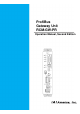
1.3 Application Example of Gateway Unit ......................................................................................... 3
1.4 Features and Key Functions ........................................................................................................ 4
1.4.1 Features ......................................................................................................................... 4
1.4.2 Key Functions ...................................................................................................................... 4
1.5 Description of Model Name ......................................................................................................... 7
1.6 Accessories ................................................................................................................................. 7
2. Specifications and Name of Each Part ...................................................................... 8
2.1 General Specifications ................................................................................................................. 8
2.2 External Dimensions .................................................................................................................... 9
2.3 Name and Function of Each Part .............................................................................................. 10
3. Installation and Noise Elimination Measures ........................................................... 16
3.1 Installation Environment. ........................................................................................................... 16
3.2 Supply Voltage .......................................................................................................................... 16
3.3 Noise Elimination Measures and Grounding ............................................................................. 16
3.4 Installation.................................................................................................................................. 18
4. Wiring ...................................................................................................................... 19
4.1 Overall Configuration ................................................................................................................. 19
4.2 I/O Signals of Gateway Unit ...................................................................................................... 22
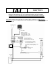
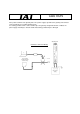
4.3 Design of SIO Communication Network (SIO Communication) ................................................ 25
4.3.1 Wiring ........................................................................................................................... 25
4.3.2 Axis Number Setting ..................................................................................................... 33
4.4 How to Connect the Teaching Tool When the Positive Terminal of the 24-V Power Supply Is
Grounded ................................................................................................................................... 34
5. Address Configuration of Gateway Unit .................................................................. 35
5.1 Position Number Specification Mode ........................................................................................ 35
5.1.1 Overall address configuration ....................................................................................... 36
5.1.2 Gateway Control/Status Signals ................................................................................... 37
5.1.3 Assignment for Each Axis ............................................................................................ 40
5.2 Direct Numerical Specification Mode ........................................................................................ 43
5.2.1 Overall Address Configuration ..................................................................................... 44
5.2.2 Gateway Control/Status Signals ................................................................................... 46
5.2.3 Assignment for each axis ............................................................................................. 49
5.3 Command Specification Mode................................................................................................... 53
5.3.1 Overall Address Configuration ..................................................................................... 55
5.3.2 Gateway Control/Status Signals ................................................................................... 57
5.3.3 Assignment for Each Axis ............................................................................................ 60
5.3.4 Command Area ............................................................................................................ 65
6 Communication Signal Details ................................................................................ 75
6.1 Overview of Communication Signal Timings ............................................................................. 75
6.2 Communication Signals and Operation Timings ....................................................................... 77
6.3 Basic Operation Timings ........................................................................................................... 85