Robo Cylinder Data Input Pendant RCM-P Operating Manual Second edition IAI America Inc.
CAUTION Disconnection of the RC Data Input Pendant from the PCON/ACON/SCON/ERC2 Controller * After disconnecting the RC Data Input Pendant from the PCON/ACON/SCON controller with the AUTO/MANU switch, always turn the AUTO/MANU switch to AUTO. * For the PCON/ACON/ERC2 controller without AUTO/MANU switch, always set the TP Operation Mode to “Monitor 2” before disconnecting the RC Data Input Pendant from the controller. (Refer to “8.10 TP Operation Mode.
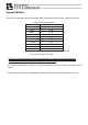
Support Models Versions of the RC Data Input Pendant RCM-P which have started support for each model are as follows. Table 1 List of Support Models Model Name Support Started Version 1 V1.00 1 V1.00 RCP * RCS * 1 V1.30 1 RCP2 * V1.63 1 V1.63 E-Con * ERC * ERC2 V2.00 PCON V2.00 ACON V2.00 SCON ROBONET V2.00 V2.08 *1: This RC Data Input Pendant also supports the RCP, RCS, E-Con, RCP2, and ERC controllers. * Confirm the connected model and version of this application (8.
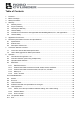
Table of Contents 1. Foreword.................................................................................................................................................... 1 2. Before You Begin ....................................................................................................................................... 1 3. Safety Precautions ..................................................................................................................................... 2 4.
9. Message Area .......................................................................................................................................... 52 9-1 Warning Label Error (Code No. 000h – 07Fh) .................................................................................. 52 9-2 RC Data Input Pendant Message Level Error.................................................................................. 53 9-3 Controller Error ...............................................................
1. Foreword Thank you very much for purchasing the RC Data Input Pendant (RCA-P) for the Robo Cylinder Controller. Without knowing beforehand how to correctly use or operate the RC Data Input Pendant, not only will the user be unable to take full advantage of all the functions built into this product but the user might also inadvertently cause damage to the Controller or shorten its life.
3. Safety Precautions (1) Use a genuine product specified by us for wiring between the actuator and controller. (2) Stand clear of the operating range of the machine when it is in motion or is ready to operate. Surround the system with safety partitions if there is a possibility that people can enter the area where the machine is being used. (3) When assembling, adjusting, or performing maintenance on the machine, always disengage the power supply to the controller.
4. Warranty 4-1 Warranty Period One of the following periods, whichever is shorter: 18 months after shipment from our company 12 months after delivery to the specified location 4-2 Scope of Warranty Our products are covered by warranty when all of the following conditions are met. Faulty products covered by warranty will be replaced or repaired free of charge: (1) The breakdown or problem in question pertains to our product as delivered by us or our authorized dealer.
4-5 Conditions of Conformance with Applicable Standards/Regulations, Etc., and Applications (1) If our product is combined with another product or any system, device, etc., used by the customer, the customer must first check the applicable standards, regulations and/or rules. The customer is also responsible for confirming that such combination with our product conforms to the applicable standards, etc.
5. Application Environment - In order to avoid breakdown, please do not apply any type of machinery impact to the RC Data Input Pendant. - Always hold onto the entire RC Data Input Pendant Body so that the RC Data Input Pendant Cable does not get pulled by unwanted cables. Caution: This RC Data Input Pendant is designed exclusively for IAI RC Controller, and should not be used to connect with other devices.
6-2 External View External Dimensions 6
6-3 Description of Each Part (1) LCD (3) (Arrow) keys (2) (4) (5) (7) (6) key key (Minus) key (Return) key (Numeric) keys 7
(1) LCD This is a liquid crystal display with a maximum of horizontal: 16 characters per column, and vertical: 2 columns per row. This displays edit and teaching contents of various set values. (2) (Arrow) keys: - This is used for selection of the mode, the contents of data and changing position No. (3) key - By pressing this key for more than 2.5 seconds, the screen will change into the “BEGIN/END” screen and you will be able to reconnect the axis and execute RC Data Input Pendant configuration.
7. Connection With the Controller 7-1 Connection with the RC Data Input Pendant (1) Connect the RC Data Input Pendant Cable to the “PORT IN” connector which is located on the front of the controller. Always turn OFF the controller Port Switch first before connecting with regard to a controller equipped with a PORT switch. (2) After connecting, turn the controller PORT Switch ON with regard to a controller equipped with a PORT switch.
8. Operation (1) Positioner (PCON-PL/PO, ACON-PL/PO, SCON: Mode other than the Pulse Train Mode) The total picture of operations performed with the RC Data Input Pendant has the tree structure as shown below. To return to the previous screen, press the ESC key. Power-ON Confirming connection TP operation mode Return * Displayed only for PCON, ACON, SCON, and ERC2.
(2) Pulse Train (PCON-PL/PO, ACON-PL/PO, SCON: Pulse Train Mode) The total picture of operations performed with the RC Data Input Pendant has the tree structure as shown below. To return to the previous screen, press the ESC key. Power-ON Confirming connection TP operation mode Return Return ESC ESC Return Reconnect Axis Select Mode Select * This is indicated only when two or more axes are connected. ESC Monitor Error List Error No. CTL error list - Error No. - Message Message Axis No.
8-1 Initial Screen During Power - UP When power is connected to the controller and the controller PORT switch is ON, power is supplied to the RC Data Input Pendant and operation starts. Once the PORT switch on the controller equipped with the PORT switch is ON, power is supplied to the RC Data Input Pendant and operation will begin. Upon power-on, the LCD display screen (hereinafter called the “screen”) displays the RC Data Input Pendant software version as follows: Confirming Link IAI RE DU V. 2.
8-2 Controller Selection (when using multiple units) In the case of multiple units connected serially via the communication line, the axis selection screen will be displayed. For a single unit, since there is no need to select the axis, the first screen below will not appear (refer to Section 8.3 entitled Operational Mode Selection of this manual). The content explained here will be based on operation of the selected axis (controller). In addition, the controller can connect up to 16 units.
8-3 Operation Mode Selection RCP, RCS, E-Con, RCP2 and ERC will be displayed as T2. PCON, SCON, ACON and ERC2 will be displayed as M2. Edit/Teach Mode Select Monitor Error List User Parameter User Adjustment TP Operation Mode RCP, RCS, E-Con, RCP2, and ERC will not be displayed. Slct Mode/M2 * Edit/Teach A. 00 Slct Mode/M2 * Monitor A. 00 Slct Mode/M2 * Error List A. 00 Slct Mode/M2 * User Parmameter A. 00 Slct Mode/M2 * User Adjustment A. 00 Slct Mode/M2 * TP Op Mode A.
Category of Modes 1. * Edit/Teach Edit and numeric input function for position data table Note: Not displayed in the case of PCON-PL/PO, ACON-PL/PO and the pulse sequence modes of SCON. 2. * Monitor RC Controller status display 3. * Error list Alarm content detailed display 4. * User Parameter Setting of axis zone signal output range and axis 5. * User Adjustment Setting for enabling or disabling of temporary stop (hold) input and the axis No. selection of RC controller. 6.
8-4 Edit/Teach 8-4-1 Edit/Teach Screen When “*Edit/Teach” is selected on the Mode Select screen, the Edit/Teach screen is displayed. The Edit/Teach screen has the 6 items as follows: * Not displayed in the case of PCON-PL/PO, ACON-PL/PO and the pulse sequence modes of SCON. Mode Select Edit/Teach MDI Monitor Clear Error List All Clear User Parameter Direct Teach User Adjustment TP Operation Mode RCP, RCS, E-Con, RCP2 and ERC will not be displayed. 16 Edit/Teach * MDI A.
You can change the screens by using the arrow keys ( * MDI: ) and press the return key. Numerically inputs the position data directly from the ten keys (input example: Page 28 in this manual). * Clear: Resets the position data (input example: Page 34 in this manual). * All Clear: Resets all of the position data (input example: Page 35 in this manual). The position data table will be displayed by selecting and determining MDI.
(2) RCP, RCS, E-Con, RCP2, ERC As the table below shows, in the position table, there are 7 setting contents (Position, Vel, Acc/Dcl, Push, Range, Acc only MAX, and ABS/INC) per each position data number. No.
8.4.2 Position Data Table Contents for PCON, ACON, SCON, and ERC2 The setting items of the position data table are No., Position, Vel, Acc/Dcl, Push, Range, LoTh, Zone+, Zone-, AccDcl Mode, Cmnd Mode, and Stop Mode. They are displayed in 10 screens. The items of Zone+, Zone-, AccDcl Mode, and Stop Mode are enabled (ON) or disabled (OFF) according to the controller type.
(3) Vel: Input the speed at which the actuator will be moved, in [mm/sec]. The initial value will depend on the actuator type. (4) Acc/Dcl: Input the acceleration/deceleration at which the actuator will be moved, in [G]. Basically, use acceleration/deceleration within the catalog rated value range. The input range allows larger value input than the catalog rated values, on the assumption that the tact time will be reduced if the transfer mass is significantly smaller than the rated value.
(6) LoTh: - This field is invalid. The default value is 0. (7) Range: - The “positioning operation” and “push operation” have different meanings. Positioning operation: It defines the distance to the target position from a position at which the position complete signal turns ON. The default value is 0.1 mm. Standard type Timing of position complete signal turning ON Since increasing the positioning width value hastens the next sequence operation, it becomes a factor for tact time reduction.
(8) Zone +/-: - It defines the zone where the zone output signal of the standard type turns ON. Individual setting is available for each target position to give flexibility. [Setting example] Position [mm] Zone+ [mm] 0 5.00 100.00 0.00 1 380.00 400.00 300.00 2 200.00 250.00 150.00 No.
S-shaped motion A curve, which is gradual at the beginning of acceleration but rises sharply halfway, is drawn. Use it in the applications for which you want to set the acceleration/deceleration high due to tact time requirement but desire a gradual curve at the beginning of movement or immediately before stop. Speed Time * Set the degree of the S-shaped motion with the parameter No. 56 [S-shaped motion ratio setting]. The setting unit is % and the setting range is between 0.0 and 100.0.
(11) Cmnd Mode: - This field is invalid. The factory setting is 0. (12) Stop Mode: - It defines the power saving method on standby after completion of positioning to the target position set in the “Position” field of the position number. 0: Invalid power saving method * The default setting is 0 (invalid). 1: Auto servo OFF method. Delay time defined with the parameter No. 36 2: Auto servo OFF method. Delay time defined with the parameter No. 37 3: Auto servo OFF method.
8-4-3 Position Data Table Contents for RCP, RCS, E-Con, and ERC The columns for the position data table are Position, Vel, Acc/Dcl, Push, Range, Acc only MAX, and ABS/INS. (1) No. Shows position data No. (2) Position: The desired move location from home in millimeters. - Absolute Positioning: Moves the actuator to the desired location in reference to the home location. Inputting negative values is not possible.
(6) Range - As for the range, depending on the setting in the push as either 0 or other than 0, this function will vary. [mm] (A) Push = 0 (Positioning Mode) - The positioning mode uses range value as a location to turn ON the position complete output prior to reaching the actual data. The default value will depend on the actuator type. (see diagram A). (B) Push ≠ besides 0 (Push Mode) - The push mode uses the range value as the distance of the push.
8-4-4 Data Input There are two methods of inputting the position data. (1) MDI numerically input ----- Method for numerically inputting the position data directly from the keypad of the Data Input Pendant. (2) Direct Teach ----- Method for allowing the position data table to read the position (current position) by turning off the servo control and manually moving the slider to adjust to the target position. In this section, we will explain an example of each operation.
(1)MDI Numeric Input Method of numerically inputting the position data directly from the ten keys of the RC Data Input Pendant. In this section, we will explain an example of the input procedure according to MDI (numeric input) for PCON, ACON, SCON and ERC2. Input the following content in Position Nos. 0 to 3. Absolute positioning mode Position 0mm Absolute positioning mode Position 50mm, Vel 100mm/s, Acc/Dcl 0.1G Range 0.2mm, Acc MAX 1 Absolute push mode Position 80mm, Vel 100mm/s, Acc/Dcl 0.
MDI Vel No. 000 125 A. 00 mm/s The screen will turn into the Input Screen for Speed. The default value will be utilized as is. Since other data will use the default value, input for position number 0 will end here. Next, position number 1 input will be executed. Input using position number 1 MDI Pos A No. 001 A. 00 * Press the key to advance the position number to 1. Position number 1 A. 00 50 The screen will turn into the Input Screen for Position. No. 001 100 A.
Input using position number 2 MDI Pos A No. 002 A. 00 * Press the key to advance the position number to 2. Position number 2 30 A. 00 80 The screen will turn into the Input Screen for Position. No. 002 100 A. 00 mm/s The screen will turn into the Input Screen for Speed. MDI Acc No. 002 0.1 A. 00 G The screen will turn into the Input Screen for Acc. MDI Dcl No. 002 0.1 A. 00 G The screen will turn into the Input Screen for Dcl. Use MDI Push % No. 002 40 A.
Input using position number 3 MDI Position A No. 003 A. 00 * Press the key to advance the position number to 3. Position number 3 Input using MDI MDI Position A No. 003 A. 00 10 The screen will turn into the Input Screen for Position. Use the Numeric keys to input 10 and then, press the Return key. MDI ABS Æ 0 No. 003 INC Æ 1 A. 00 1 Press the key to change screen into ABS/INC MDI Position I No. 003 A. 00 10.00 The screen will turn into the Input Screen for Position. Display Screen.
(2) Direct Teach Manually move the slider or rod to adjust it to the target position, and allow the position data table to read the current position. In this example, input data in Position No. 4 by Direct Teach. Slct Mode/M2 * Edit/Teach A. 00 Edit/Teach * Direct Teach A. 00 Using the keys in the Mode Select Screen, select Edit/Teach and choose using the Return key. Using the keys in the Edit/Teach Screen, select Direct Teach and choose using the Return key.. Direct Teach Srv OFF A. 00 51.
8-4-5 Clear • All Clear In this section, we will give specific examples of how to clear data in the position table. (1) Clear: Resets the assigned position data. (2) All Clear: Resets all of 16 position data.
(1) Clear: The Clear operation procedure is explained below. The data of any position number is cleared. In this example, the data of position number 1 is cleared. The position data table becomes as shown below. No. Position 0 0.00 1 50.00 2 80.00 3 10.00 No. Position 0 0.00 1 * 2 80.00 3 10.00 Vel Acc Dcl Push LoTh Range 0.20 G 0.20 G 0% 0% 0.10 mm 0.10 G 0.10 G 0% 0% 0.20 mm 0.10 G 0.10 G 40 % 0% 5.00 mm 0.20 G 0.20 G 0% 0% 0.
(2) All Clear: The data of all the position numbers is cleared. The position data table becomes as shown below. No. Position 0 0.00 1 50.00 2 80.00 3 10.00 Vel 125 mm/s 100 mm/s 100 mm/s 20 mm/s Acc Dcl Push LoTh Range 0.20 G 0.20 G 0% 0% 0.10 mm 0.10 G 0.10 G 0% 0% 0.20 mm 0.10 G 0.10 G 40 % 0% 5.00 mm 0.20 G 0.20 G 0% 0% 0.10 mm Zone + Zone - 0.00 mm 0.00 mm 0.00 mm 0.00 mm 0.00 mm 0.00 mm 0.00 mm 0.
8-4-6 Data Modification You may write over all of the position data. (1) Manual Input: Manually enter the position data directly from the RC Data Input Pendant key pad. (2) Direct Teach: Turn the servo OFF, manually move the slider to the desired location, and read that location into the position table. Caution during data modification: * As for manual input, the data entered will erase the old data.
8-5 Monitor The I/O status and current position of all controllers connected on the communications line will be displayed. Slct Mode/M2 * Monitor A. 00 In the Mode Select Screen, using the keys, select Monitor and then, press the Return key. Select the displayed item using the Return key or the keys. Use the keys to change the axis number. The following is a display example of controller PCON-CY. Some of the screen may not be displayed depending on the type of controller.
Monitor out 02 LS2 A. 00 OFF Displays the LS3 (intermediate point end position Monitor out 03 SV A. 00 OFF Displays the SV (operating preparation completion) Monitor out 04 HEND A. 00 ON Displays the HEND (homing completion) status. Monitor out 05 * ALM A. 00 ON * Displays the ALM (alarm output) status. detection) status. status. Displays ON if homing is completed, and displays OFF if not. Displays ON when it is normal. Displays special input port hereinafter.
8-6 Error List As long as the RC Data Input Pendant is connected, this display will show the content of the controller error. Slct Mode/M2 * Err List A. 00 In the Mode Select Screen, using the keys, select Error List and then, press the Return key. (1) RC Data Input Pendant error list Displays the error having occurred after the RC Data Input Pendant connection (PORT ON). Select the displayed item using the Return key or keys. Change the list number using the keys. Error list totaled 30 (List No.
(2) Controller error list Press any one of the ten keys 0-8 from the screen of the RC Data Input Pendant error list, then the error that has occurred is displayed after power for the controller is turned ON. For a number of 10 or more, press the key and the ten keys of 0-5. Note) The RC Data Input Pendant FLASH Ver. 1.63 and later make available the display function of the controller error list. For PCON, ACON, SCON and ERC2, the content of the alarm list will be kept even if the power is turned OFF.
8-7 User Parameter The User parameter assigns zone and soft limit ranges, actuator attributes and home direction. Zone and soft limit are set within ±9999.99 (input unit: mm). Home and servo parameters are determined by the actuator. Each setting for initial setting value parameters is the registered default value for position data during teaching. Slct Mode/M2 * User Parm A. 00 In the Mode Select Screen, using the keys, select User Parameter and then, press the Return key.
42 User Parm 12 Hold Cur A. 00 5% Sets the current limit value when positioning stops. User Parm 13 Home Cur A. 00 10% Sets the current limit value when homing is carried User Parm 16 Baud A. 00 38400bps User Parm 17 RTIM A. 00 5 msec User Parm 21 SON Disable A. 00 1 User Parm 22 OFST A. 00 0.20mm User Parm 23 + Zone 2 A. 00 9999.99mm Sets the zone limit 2 + side. User Parm 24 - Zone 2 A. 00 9999.99mm Sets the zone limit 2 − side. User Parm 25 PIO Ptn A. 00 0 Sets the PIO pattern.
User Parm 35 Safty Vel A. 00 250mm/s User Parm 36 Auto Srv Off A. 00 0s Sets the auto servo OFF delay time 1. User Parm 37 Auto Srv Off 2 A. 00 0s Sets the auto servo OFF delay time 2. User Parm 38 Auto Srv Off 3 A. 00 0s Sets the auto servo OFF delay time 3. User Parm 39 PEND Output Typ A. 00 0 Sets the positioning complete signal output method User Parm 42 Enable Fnc Dis A. 00 1 Sets the enable function [0: enable/1: disable]. User Parm 43 Home Sensor Dis A.
- When soft limit is modified at the customer site, please set a value which extends 0.3mm outside of the effective area. Example: When setting the effective area between 0mm~80mm Soft limit + side: 80.3 Soft limit - side: -0.3 Soft Limit set in controller Approx. 0.3mm Approx. 0.3mm Effective area Approx. 0.1mm Approx. 0.1mm Jog Increment allowable range after homing - For RCP, RCS, E-Con, RCP2 and ERC, if the homing direction is changed, all of the inputted position data will be cleared.
8-8 Software reset after user parameters are changed For software reset (re-start) function support model (PCON, ACON, ERC2, RCP2, ERC), the screen moves to the software reset screen when the key is pressed after the user parameter is changed or the user adjustment is set. Soft Reset * Reset? YÆ1 A. 00 NÆ0 Press 1 when resetting the software. (Press 0 when interrupting to reset the software. The screen returns to the mode select screen.) Soft Reset * Srv OFF? YÆ1 A.
8-9 User Adjustment 8-9-1 Pause, servo ON input enable and disable setting, axis number setting Sets enable or disable pause. Sets the axis number of controllers (PCON, ACON, ERC2, RCP-RSI, RCP-RMI, ERC, etc.) Slct Mode/M2 * User Adjust A. 00 Enable hold input: User Adjust Adjust keys, select User Adjustment and then, press the Return key. Disable hold input: User Adjust Adjust In the Mode Select Screen, using the A. 00 91 Input 91 A.
Setting the controller axis number Sets the axis numbers of controllers (RCP, ERC, ERC2) and compact types (PCON-CY, SE, PL/PO, ACON-CY, SE, PL/PO). User Adjust alloc. A. 00 0 Input axis number. User Adjust Adjust A. 00 2 Input 2 The adjustment No. and allocation No. are changed by pressing the Return key or keys. Input the axis number into the allocation number and then, press the Return key. Input 2 into the adjustment number and then, press the Return key. If axis No.
8-9-2 Software Reset Resets the software (re-start up the controller). * Version V2.00 or later make available the software reset function. It is ready for models of PCON, ACON, SCON, RCP2, ERC and ERC2. Slct Mode/M2 * User Adjust A. 00 In the mode select screen, using the keys, select User Adjustment, and then press the Return key. User Adjust Adjust A. 00 4 Input 4 into the adjustment number, and press the Soft Reset * Reset? A.
8-9-3 Error List Clear Clears all of the contents of error lists in the controller. * Version V2.00 and later make available the error list clear function. This is available for models of PCON, ACON, SCON, and RCP2. Slct Mode/M2 * User Adjust A. 00 In the mode select screen, using the keys, select User Adjustment, and then press the Return key. User Adjust Adjust A. 00 3 Input 3 into the adjustment number, and press the Soft Reset * Reset? A. 00 NÆ0 Press the YÆ1 Return key. key.
8-10 TP Operation Mode Sets operation mode in the manual mode (MANU). Models of PCON, ACON, SCON, ERC2 are available for this mode. Slct Mode/M2 * TP Op Mode TP Op Mode Slct (Å, Æ): A. 00 In the mode select screen, using the select User Adjustment, and then press the Return key. A. 00 Teach 1 The TP operation mode is selected from the following four menus using the - keys, keys. Teach 1 PIO not allowed: It is allowed to write position data and parameters, etc.
8-11 End End is executed to save each setting or registration content of the RC Data Input Pendant. Before removing the RC Data Input Pendant from the RC controller, be sure to execute End. Operation: Press the key for more than 2.5 seconds. In a case that data input ends, and the RC In a case that you reopen the connection from Data Input Pendant needs to be removed the initial screen Op. Start / End * End Op. Start / End * End DU = Efct Op.
9. Message Area In the message screen, content during error and warning will be displayed. Code No. Error Label Error Reset Reference 000~07F Controller Warning Yes Controller rejects command 080-0FF Controller Error Yes Error inside the controller 100~1FF DIP* Message Yes Input error, guide message, etc. 200~2FF DIP* Movement Release Yes Movement continuation impossible 300~3FF DIP Cold Start Error No DIP Power install or reconnect are necessary.
9-2 RC Data Input Pendant Message Level Error RC Data Input Pendant Operational Mistake: When you attempt to input an incorrect value, the message label error will occur. Code No: 112h, 113h, 114h, 118h, 11Eh, 11Fh, etc. (Keypad input value is incorrect.) 9-3 Controller Error An alarm detected from the controller side can be displayed. This is a serious error due to an abnormality related to servo control and electricity.
Appendix * Appendix Parameter (factory-installed) initializing method Parameter is changed to the factory-installed parameter. (Initialization) Models of PCON, ACON, SCON, ERC2 are available for this method. Caution: Note that the parameter set by the user is changed to the factory-installed parameter if the parameter (factory-installed) is initialized. Slct Mode/M2 * User Adjust User Adjust Adjust Ship Para * Reset? A.
Appendix Soft Reset * Srv OFF? YÆ1 A. 00 NÆ0 When servo is turned ON, you are asked whether servo off is carried out or not on all screens by pressing the key. (When interrupting the software reset, press the key. The screen returns to the mode select screen.) Soft Reset * Please Wait. A. 00 A message “data being obtained” appears, the software is reset, and operation is performed with parameters set at shipment from factory. After executing, the screen returns to the mode select screen.
Appendix RC Data Input pendant error table Listed on the table are RC Data Input Pendant specific error. For error of controller, refer to the Operating Manual of each controller. Code Message name Description 112 Input Incorrect Error 113 114 Input Under Error Input Over Error 115 Homing Incomplete 117 No Move Data 11E Pair Data Mismatch 11F Absolute Value Error 121 Push search end over 122 Allocate, multi-axes connect 133 Jig No.
Appendix Code Message name 20D During movement, STP-OFF 20E Soft limit over 210 During movement, HOME-ON During movement operation, homing signal (HOME) from PLC side is turned ON, and movement command is duplicated. During movement, JOG-ON During movement operation, jog movement signal (JOG) from PLC side is turned ON, and movement command is duplicated. During AUTO, write not Parameter writing operation was performed in AUTO mode of PCON-C/CG, allowed ACON-C/CG, SCON controllers.
Revision Date Description of Revision First edition January 2012 66 Second edition Support Models: ROBONET added P. 3 : Contents changed is Warranty P.
Manual No.: ME0175-2A (January 2012) Head Office: 577-1 Obane Shimizu-KU Shizuoka City Shizuoka 424-0103, Japan TEL +81-54-364-5105 FAX +81-54-364-2589 website: www.iai-robot.co.jp/ Technical Support available in USA, Europe and China Head Office: 2690 W.