ROBO Cylinder RCP2 Actuator ROBO Rotary Type Small Type, 330-degree Rotation Specification [RTBS/RTCS Types] Small Type, Multi-rotation Specification [RTBSL/RTCSL Types] Medium Type, 330-degree Rotation Specification [RTB/RTC Types] Medium Type, Multi-rotation Specification [RTBL/RTCL Types] Large Type, 330-degree Rotation Specification [RTBB/RTCB Types] Large Type, Multi-rotation Specification [RTBBL/RTCBL Types] Operating Manual Ninth Edition Seventh Edition IAI America, Inc.
Please Read Before Use Thank you for purchasing our product. This Operation Manual explains the handling methods, structure and maintenance of this product, among others, providing the information you need to know to use the product safely. Before using the product, be sure to read this manual and fully understand the contents explained herein to ensure safe use of the product. The CD or DVD that comes with the product co ntains operation manuals for IAI products.
CE Marking If a compliance with the CE Marking is required, please follow Overseas Standards Compliance Manual (ME0287) that is provided separately.
Prohibited Handling of Cables When designing an application system using IAI actuators and controllers, incorrect wiring or connection of each cable may cause unexpected problems such as a disconnected cable or poor contact, or even a runaway system. This section explains prohibited handling of cables. Read the information carefully to connect the cables properly. Ten Rules for Handling Cables (Must be Observed!) 1. Do not let the cable flex at a single point. Steel band (piano wire) Bundle loosely. 2.
7. Notes on use of cable bearers z The supplied cable is not a robot cable. Accordingly, never store the supplied cable in a cable bearer. z If a relay cable is to be used, always use a robot cable. Bending radius r z Use a cable bearer with its bending radius r set to 50 mm or greater. z Do not let the cable get tangled or kinked in a cable bearer or flexible tube. When bundling the cable, keep a certain degree of flexibility (so that the cable will not become too taut when bent).
Table of Contents Safety Guide ................................................................................................................................. 1 Caution in Handling ...................................................................................................................... 8 1. Introduction............................................................................................................................. 9 2. Safety Precautions ..........................................
. Cable Connection ................................................................................................................ 33 8.1 Connecting the Controller ..................................................................................................... 33 8.2 Checks after Installation ...................................................................................................... 33 9. Notes on Use .....................................................................................
Safety Guide ³6DIHW\ *XLGH´ KDV EHHQ ZULWWHQ WR XVH WKH PDFKLQH VDIHO\ DQG VR SUHYHQW SHUVRQDO LQMXU\ RU SURSHUW\ GDPDJH EHIRUHKDQG 0DNH VXUH WR UHDG LW EHIRUH WKH RSHUDWLRQ RI WKLV SURGXFW Safety Precautions for Our Products 7KH FRPPRQ VDIHW\ SUHFDXWLRQV IRU WKH XVH RI DQ\ RI RXU URERWV LQ HDFK RSHUDWLRQ 1R 2SHUDWLRQ 'HVFULSWLRQ 0RGHO 6HOHFWLRQ 'HVFULSWLRQ Ɣ 7KLV SURGXFW KDV QRW EHHQ SODQQHG DQG GHVLJQHG IRU WKH DSSOLFDWLRQ ZKHUH KLJK OHYHO RI VDIHW\ LV UHTXLUHG VR WKH JXDUDQWHH RI WKH
No. 2 2 Operation Description Transportation 3 Storage and Preservation 4 Installation and Start Description Ɣ When carrying a heavy object, do the work with two or more persons or utilize equipment such as crane. Ɣ When the work is carried out with 2 or more persons, make it clear who is to be the leader and who to be the follower(s) and communicate well with each other to ensure the safety of the workers.
No. 4 Operation Description Installation and Start Description (2) Cable Wiring Ɣ 8VH RXU FRPSDQ\¶V JHQXLQH FDEOHV for connecting between the actuator and controller, and for the teaching tool. Ɣ Do not scratch on the cable. Do not bend it forcibly. Do not pull it. Do not coil it around. Do not insert it. Do not put any heavy thing on it. Failure to do so may cause a fire, electric shock or malfunction due to leakage or continuity error.
No. 4 4 Operation Description Installation and Start 7HDFKLQJ Description (4) Safety Measures Ɣ When the work is carried out with 2 or more persons, make it clear who is to be the leader and who to be the follower(s) and communicate well with each other to ensure the safety of the workers.
No. 6 7 Operation Description Trial Operation Automatic Operation Description Ɣ When the work is carried out with 2 or more persons, make it clear who is to be the leader and who to be the follower(s) and communicate well with each other to ensure the safety of the workers. Ɣ After the teaching or programming operation, perform the check operation one step by one step and then shift to the automatic operation.
No. 8 9 6 Operation Description Maintenance and Inspection 10 Modification and Dismantle Disposal 11 Other Description Ɣ When the work is carried out with 2 or more persons, make it clear who is to be the leader and who to be the follower(s) and communicate well with each other to ensure the safety of the workers. Ɣ Perform the work out of the safety protection fence, if possible.
Alert Indication 7KH VDIHW\ SUHFDXWLRQV DUH GLYLGHG LQWR ³'DQJHU´ ³:DUQLQJ´ ³&DXWLRQ´ DQG ³1RWLFH´ DFFRUGLQJ WR WKH ZDUQLQJ OHYHO DV IROORZV DQG GHVFULEHG LQ WKH 2SHUDWLRQ 0DQXDO IRU HDFK PRGHO /HYHO 'HJUHH RI 'DQJHU DQG 'DPDJH 'DQJHU 7KLV LQGLFDWHV DQ LPPLQHQWO\ KD]DUGRXV VLWXDWLRQ ZKLFK LI WKH SURGXFW LV QRW KDQGOHG FRUUHFWO\ ZLOO UHVXOW LQ GHDWK RU VHULRXV LQMXU\ 'DQJHU :DUQLQJ 7KLV LQGLFDWHV D SRWHQWLDOO\ KD]DUGRXV VLWXDWLRQ ZKLFK LI WKH SURGXFW LV QRW KDQGOHG FRUUHFWO\ FRXOG UH
Caution in Handling 1. Do not set speeds and accelerations/decelerations equal to or greater than the respective ratings. If the actuator is operated at a speed or acceleration/deceleration exceeding the allowable value, abnormal noise or vibration, failure, or shorter life may result. In the case of interpolated operation of combined axes, the speed and acceleration/deceleration settings should correspond to the minimum values among all combined axes. 2. Keep the load moment within the allowable value.
1. Introduction 2. 2.1 1. Introduction Thank you for purchasing IAI’s Robo Rotary actuator. This manual explains the correct handling of the actuator as well as its structure, maintenance and other items the user should know about the Robo Rotary. Before using the Robo Rotary, be sure to read this manual and ensure the correct handling of the actuator.
3. Warranty 3.1 Warranty Period 3. Warranty One of the following periods, whichever is shorter: y 18 months after shipment from our company y 12 months after delivery to the specified location 3.2 Scope of Warranty Our products are covered by warranty when all of the following conditions are met. Faulty products covered by warranty will be replaced or repaired free of charge: (1) The breakdown or problem in question pertains to our product as delivered by us or our authorized dealer.
3.5 Conditions of Conformance with Applicable Standards/Regulations, Etc., and Applications (1) If our product is combined with another product or any system, device, etc., used by the customer, the customer must first check the applicable standards, regulations and/or rules. The customer is also responsible for confirming that such combination with our product conforms to the applicable standards, etc.
4. Names of Actuator Parts The name of each part of the actuator is shown as follows. Small Type 4.1.1 330-degree Rotation Specification RTBS, Multi-rotation Specification RTBSL (Vertical Type) 4. Names of Actuator Parts 4.
4.1.2 330-degree Rotation Specification RTCS, Multi-rotation Specification RTCSL (Flat Type) Actuator cable Front cover 4.
4. Names of Actuator Parts 4.2 Medium Type 4.2.
4.2.2 330-degree Rotation Specification RTC, Multi-rotation Specification RTCL (Flat Type) Actuator cable Front cover 4.
4. Names of Actuator Parts 4.3 Large Type 4.3.
4.3.2 330-degree Rotation Specification RTCB, Multi-rotation Specification RTCBL (Flat Type) Actuator cable Front cover 4.
5. Transportation and Handling 5.1 Handling the Packed Actuator When transporting the packed actuator, exercise due caution not to apply impact on the package by dropping it or hitting it against other object. 5. Transportation and Handling x x x x A person should never attempt to carry a heavy package on his own. When setting down the package temporarily, keep it horizontal. Do not step onto the package.
6. 6.1 Installation Environment, Storage Environment Installation Environment Install the actuator in an environment meeting the conditions listed below. 6.2 6. Installation Environment, Storage Environment x not be exposed to direct sunlight. x be free from irradiating heat coming from a heat treatment furnace or other equipment that generates a large amount of heat. x have ambient temperature of 0 to 40qC. x have humidity of 85% or below (non-condensing). x be free from corrosive or flammable bases.
7. Installation Method 7.1 Installing the Actuator The surface on which the actuator is installed must be machined or otherwise have a flat surface of equivalent accuracy. This actuator is constructed to allow installation on its three different sides. x The maximum screw-in depth varies depending on the mounting surface. Determine the length of applicable screws by referring to the figures shown on the pages that follow. Caution 7.
7.1.1 Small Type x 330-degree Rotation Specification RTBS, Multi-rotation Specification RTBSL (Vertical Type) depth 4 13 Flange-side mounting surface 4-M3, depth 3.5 3H7 depth 4 4-M3, depth 7 depth 2.5 4-M3, depth 5.5 4-M3, depth 5.5 depth 7.5 7. Installation Method depth 2.5 depth 2.5 Side mounting surface 3 depth 2.5 Bottom mounting surface Caution x Some of the tapped mounting holes are through holes.
x 330-degree Rotation Specification RTCS, Multi-rotation Specification RTCSL (Flat Type) 13 7. Installation Method depth 4 depth 2.5 4-M3, depth 7 3 4-M3, depth 3.5 depth 2.5 4-M3, depth 5.5 depth 4 Flange-side mounting surface Bottom mounting surface depth 7.5 depth 2.5 4-M3. depth 5.5 depth 2.5 6 through hole 11, depth 0.9 Side mounting surface Caution x Some of the tapped mounting holes are through holes.
depth 3 7.1.2 Medium Type x 330-degree Rotation Specification RTB, Multi-rotation Specification RTBL (Vertical Type) 17 Flange-side mounting surface 5-M3, depth 6 3H7, depth 4 4-M4, depth 7 depth 2.5 11H7,depth 10 4-M4, depth 8 7. Installation Method depth 2.5 depth 2.5 4-M4, depth 8 Side mounting surface depth 2.5 Bottom mounting surface Caution x Some of the tapped mounting holes are through holes.
x 330-degree Rotation Specification RTC, Multi-rotation Specification RTCL (Flat Type) depth 3 depth 2.5 17 5-M3, depth 6 3H7 depth 4 7. Installation Method 4-M4, depth 7 Flange-side mounting surface depth 2.5 4-M4, depth 8 Bottom mounting surface 11H7 depth 10 depth 2.5 4-M4, depth 8 10 through hole depth 2.5 15.4 depth 5.5 Side mounting surface Caution x Some of the tapped mounting holes are through holes.
7.1.3 Large Type x 330-degree Rotation Specification RTBB, Multi-rotation Specification RTBBL (Vertical Type) 30 depth 5 depth 5 4-M5, depth 8.6 Flange-side mounting surface 6-M4, depth 7 depth 12.5 depth 3.5 4-M5, depth 10 7. Installation Method depth 3.5 4-M5 depth 10 depth 3.5 Side mounting surface depth 3.5 Bottom mounting surface Caution x Some of the tapped mounting holes are through holes.
depth 5 x 330-degree Rotation Specification RTCB, Multi-rotation Specification RTCBL (Flat Type) depth 3.5 14 30 4-M5, depth 8.6 4-M5, depth 10 7. Installation Method 6-M4, depth 7 depth 5 Flange-side mounting surface depth 3.5 Bottom mounting surface depth 12.5 depth 3.5 4-M5, depth 10 depth 3.5 20 through hole 27, depth 3.5 Side mounting surface Caution x Some of the tapped mounting holes are through holes.
7.2 Output Shaft Adapters (Optional) The external dimensions of adapters that can be installed on the actuator’s output shaft are shown below. 7.2.1 Small Type x 330-degree Rotation Specification RTBS, Multi-rotation Specification RTBSL (Vertical Type) depth 4 30 Table adapter 4-M3, depth 7 Table adapter 6-M3,depth 7 depth 0.5 depth 4 7.
x 330-degree Rotation Specification RTCS, Multi-rotation Specification RTCSL (Flat Type) Table adapter depth 4 30 6-M3,depth 7 4-M3, depth 7 Table adapter depth 0.5 7. Installation Method depth 2.5 4-M3, depth 5.5 depth 2.5 6 through hole 11, depth 0.9 depth 4 Shaft adapter 4-M3, depth 7 Shaft adapter depth 2.5 28 depth 2.5 4-M3, depth 5.
7.2.2 Medium Type x 330-degree Rotation Specification RTB, Multi-rotation Specification RTBL Table adapter 8-M4, depth 7.5 34 depth 1.5 Table adapter 7.
x 330-degree Rotation Specification RTC, Multi-rotation Specification RTCL Table adapter 8-M4, depth 7.5 34 7. Installation Method Table adapter depth 1.5 10 through hole 15.4, depth 5.
Table adapter 4-M5, depth 8.6 depth 5 7.2.3 Large Type x 330-degree Rotation Specification RTBB, Multi-rotation Specification RTBBL (Vertical Type) 52 8-M5, depth 9 depth 1.5 7. Installation Method 48-M5, depth 8.
x 330-degree Rotation Specification RTCB, Multi-rotation Specification RTCBL (Flat Type) Table adapter 8-M5, depth 9 14 depth 5 52 4-M5, depth 8.6 Table adapter depth 1.5 7. Installation Method depth 3.5 depth 10 depth 3.5 14 Shaft adapter 20 through hole 27, depth 3.5 depth 5 4-M5, depth 8.6 Shaft adapter depth 3.5 depth 3.
8. 8.1 Cable Connection Connecting the Controller Plug the connector attached at the end of the actuator cable into the controller. Take note of the following points when connecting the actuator cable. x If the actuator cable cannot be affixed, allow it to droop or wire it along a self-standing cable hose or along a large radius to minimize the load received by the cable. x Do not cut the cable to extend or shorten its length or reconnect the cut cables together.
9. Notes on Use 9.1 Range of Operation and Home Return z Range of operation (position setting) The angle of movement from the home position determines the position value. x 330-degree rotation specification: Position specification range = 0 to 330 degrees x Multi-rotation specification: Position specification range = As specified below. * Mode Absolute position specification Relative position specification Rotational axis, normal mode -0.15 to +9999.15 -9999.30 to +9999.
z Home return direction The moving end of the output shaft, which turns in the counterclockwise direction, is defined as the home. * The multi-rotation specification is available with the direction of axis rotation reversed. On an actuator with the reverse-rotation specification, home return is implemented in the clockwise direction.
z Home return operation x 330-degree rotation specification [1] Start of home return o [2] Detection of a mechanical stopper o [3] Reversing o [4] Movement by a specified offset o [5] Home position Range of operation (330q) Home return Home (end of forward rotation) Movement by a specified offset [5] [1] [2] [4] [3] Mechanical stopper Rotating axis 330-degree rotation specification RTB/RTC 9. Notes on Use Caution x The actuator always rotates in the specified direction during home return.
x Multi-rotation specification PCON controller PSEL controller V 0018 or earlier V 0.
x Multi-rotation specification PCON controller V 0019 or earlier PSEL controller V 0.
9.2 Output Torque 9.2.1 Small Type The output torque of the rotating axis will vary depending on the rotational speed of the axis. Output torque (N-m) 330-degree rotation specification RTBS/RTCS (deceleration ratio: 1/30) Multi-rotation specification RTBSL/RTCSL (deceleration ratio: 1/30) Rotational speed (q/sec) 9.
9.2.2 Medium Type The output torque of the rotating axis will vary depending on the rotational speed of the axis. Output torque (N-m) 330-degree rotation specification RTB/RTC (deceleration ratio: 1/20) Multi-rotation specification RTBL/RTCL (deceleration ratio: 1/20) Rotational speed (q/sec) Output torque (N-m) 9.
9.2.3 Large Type The output torque of the rotating axis will vary depending on the rotational speed of the axis. Output torque (N-m) 330-degree rotation specification RTBB/RTCB (deceleration ratio: 1/20) Multi-rotation specification RTBBL/RTCBL (deceleration ratio: 1/20) Rotational speed (q/sec) 9.
9.3 Allowable Load 9.3.1 Small Type z Allowable inertial moment The maximum inertial moment of the work that can be carried in rotating motion using the actuator will vary depending on the rotational speed. Design the work after checking the operating condition and inertial moment. 9.
z Allowable load moment/thrust force Check if the load moment and thrust force received by the rotational axis are within the allowable ranges specified below. Model 330-degree rotation specification RTBS/RTCS Multi-rotation specification RTBSL/RTCSL Allowable load moment Allowable thrust force 3.6 N-m 30 N Load moment Thrust force 9.
9.3.2 Medium Type z Allowable inertial moment The maximum inertial moment of the work that can be carried in rotating motion using the actuator will vary depending on the rotational speed. Design the work after checking the operating condition and inertial moment. Inertial moment (x10-3 kg-m2) 330-degree rotation specification RTB/RTC (deceleration ratio: 1/20) Multi-rotation specification RTBL/RTCL (deceleration ratio: 1/20) 9.
z Allowable load moment/thrust force Check if the load moment and thrust force received by the rotational axis are within the allowable ranges specified below. Model 330-degree rotation specification RTB/RTC Multi-rotation specification RTBL/RTCL Allowable load moment Allowable thrust force 3.9 N-m 50 N Load moment Thrust force 9.
9.3.3 Large Type z Allowable inertial moment The maximum inertial moment of the work that can be carried in rotating motion using the actuator will vary depending on the rotational speed. Design the work after checking the operating condition and inertial moment. Inertial moment (x10-3 kg-m2) 330-degree rotation specification RTBB/RTCB (deceleration ratio: 1/20) Multi-rotation specification RTBBL/RTCBL (deceleration ratio: 1/20) 9.
z Allowable load moment/thrust force Check if the load moment and thrust force received by the rotational axis are within the allowable ranges specified below. Model 330-degree rotation specification RTBB/RTCB Multi-rotation specification RTBBL/RTCBL Allowable load moment Allowable thrust force 17.7 N-m 200 N Load moment Thrust force 9.
10. Maintenance/Inspection Daily and periodic inspections are essential to making sure your actuator will operate safely and efficiently. Before carrying out each inspection, check the applicable maintenance/inspection items listed below. 10.1 Inspection Items and Timings Conduct visual inspection and add grease at the applicable timings specified below. The following schedule is based on eight hours of operation daily.
10.2 Visual Inspection of the Exterior In the visual inspection of the exterior, check the following items. Actuator Cables Overall 10.3 Loosening of actuator mounting bolts, etc. Scratches, proper connection of connectors Noise, vibration Exterior Cleaning x Clean the exterior of the actuator as necessary. x Use a soft cloth, etc., to wipe off dirt. x Do not blow compressed air onto the actuator too strongly, in order to prevent dust from entering the actuator through small openings and gaps.
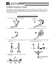
(2) Greasing method [1] Remove the screws on the front cover (countersunk head screw M2.6 x 6), and take off the front cover. RTBS, RTBSL RTB, RTBL RTBB, RTBBL 10. Maintenance/Inspection [2] (Flat type) Remove the screws on the rear cover (countersunk head screw M2.6 x 6), and separate the rear cover from the actuator (do not forcibly pull the cables inside). The rear cover remains attached to the actuator through the cables.
[3] While turning the gear, add grease from the opening in the rear until the bottom of the teeth is covered with grease. (Turn the input shaft to turn the output gear.) Once a sufficient amount of grease has been added, move the gear back and forth several times to evenly spread grease. Small type RTBS, RTBSL (Vertical type) Turn. Turn. RTCS, RTCSL (Flat type) (rear opening) 10. Maintenance/Inspection RTBS, RTBSL (Vertical type) (rear opening) RTCS, RTCSL (Flat type) Add grease to the gear.
While turning the gear, add grease from the opening in the rear until the bottom of the teeth is covered with grease. (Turn the input shaft to turn the output gear.) Once a sufficient amount of grease has been added, move the gear back and forth several times to evenly spread grease. Medium type RTB, RTBL (Vertical type) RTC, RTCL (Flat type) Turn. Turn. RTB, RTBL (Vertical type) (rear opening) RTC, RTCL (Flat type) (rear opening) 10. Maintenance/Inspection Add grease to the gear.
While turning the gear, add grease from the opening in the rear until the bottom of the teeth is covered with grease. (Turn the input shaft to turn the output gear.) Once a sufficient amount of grease has been added, move the gear back and forth several times to evenly spread grease. Large type RTBB, RTBBL (Vertical type) Turn Turn (rear opening) 10. Maintenance/Inspection RTBB, RTBBL (Vertical type) RTCB, RTCBL (Flat type) RTCB, RTCBL (Flat type) (rear opening) Add grease to the gear.
[4] Install the front cover and rear cover and securely tighten the screws. When attaching the rear cover, exercise caution not to pinch the cables between the cover and actuator. Warning 10. Maintenance/Inspection • Never use fluorine grease. If fluorine grease is mixed with lithium grease, the lubricating function of grease will drop and the machine may suffer damage due to increased friction. • Do not add grease more than necessary.
11. Specifications 11.1 Specification List 11.1.1 Small Type 330-degree specification Model number Vertical Flat Deceleration Oscillation ratio angle (deg) Maximum speed (deg/sec) Maximum torque (N-m) Allowable inertial moment 2 (kg-m ) RCP2-RTBS-I-20P-30-330 1/30 330 400 0.24 0.0023 RCP2-RTBS-I-20P-45-330 1/45 330 266 0.36 0.0035 RCP2-RTCS-I-20P-30-330 1/30 330 400 0.24 0.0023 RCP2-RTCS-I-20P-45-330 1/45 330 266 0.36 0.
11.1.2 Medium Type 330-degree specification Model number Vertical Flat Deceleration Oscillation ratio angle (deg) Maximum speed (deg/sec) Allowable Maximum inertial moment torque (N-m) 2 (kg-m ) RTB-I-PM-28P-20-330 1/20 330 600 1.1 0.01 RTB-I-PM-28P-30-330 1/30 330 400 1.7 0.015 RTC-I-PM-28P-20-330 1/20 330 600 1.1 0.01 RTC-I-PM-28P-30-330 1/30 330 400 1.7 0.
11.1.3 Large Type 330-degree specification Model number Vertical Flat Deceleration Oscillation ratio angle (deg) Maximum Maximum Allowable speed torque inertial moment 2 (deg/sec) (N-m) (kg-m ) RCP2-RTBB-I-35P-20-330 1/20 330 600 3 0.02 RCP2-RTBB-I-35P-30-330 1/30 330 400 4.6 0.03 RCP2-RTCB-I-35P-20-330 1/20 330 600 3 0.02 RCP2-RTCB-I-35P-30-330 1/30 330 400 4.6 0.
11.2 Cable Diagrams 11.2.1 Small Type, 330-degree Rotation Specification [RTBS, RTCS] Small Type, Multi-rotation Specification [RTBSL, RTCSL] [1] Integrated motor/encoder cable (Front view) (Front view) Controller end Actuator end Signal Pin No.
11.2.
11.3 External Dimensions 4-M3, depth 5.5 depth 2.5 depth 2.5 4-M3, depth 5.5 depth 7.5 ∅ 4-M3, depth 7 4-M3, depth 3.5 ∅ ∅13 ∅ ∅ ∅ 6SHFL¿FDWLRQV depth 4 ∅ depth 2.5 depth 2.5 11.3.1 Small Type • 330-degree Rotation Specification RTBS, Multi-rotation Specification RTBSL (Vertical Type) Weight [kg] 60 0.
∅ depth 2.5 ∅ ∅ ∅30 Weight [kg] ∅6 through hole ∅11, depth 0.9 depth 0.5 depth 2.5 4-M3, depth 5.5 ∅ depth 7 6SHFL¿FDWLRQV 4-M3, depth 7 ∅ depth 2.5 depth 2.5 4-M3, depth 5.5 • 330-degree Rotation Specification RTCS, Multi-rotation Specification RTCSL (Flat Type) 0.
depth 2.5 ∅11H7, depth 10 Weight [kg] 62 depth 2.5 ∅ 4-M4, depth 8 4-M4, depth 7 5-M3, depth 6 ∅ depth 3 ∅ ∅3H7, depth 4 6SHFL¿FDWLRQV ∅ depth 8 depth 2.5 depth 2.5 11.3.2 Medium Type • 330-degree Rotation Specification RTB, Multi-rotation Specification RTBL (Vertical Type) 0.
Weight [kg] depth 2.5 15.4, depth 5.5 10 through hole 11H7, depth 10 depth 2.5 4-M4, depth 8 3H7, depth 4 6SHFL¿FDWLRQV 4-M4, depth 7 depth 3 5-M3, depth 6 depth 2.5 4-M4, depth 8 depth 2.5 330-degree Rotation Specification RTC, Multi-rotation Specification RTCL (Flat Type) 0.
64 6-M4, depth 7 4-M5, depth 8.6 ∅30 depth 3.5 ∅ ∅ Weight [kg] depth 3.5 depth 12.5 depth 5 4-M5, depth 10 ∅ ∅ ∅ 6SHFL¿FDWLRQV ∅ depth 3.5 depth 3.5 4-M5, depth 10 11.3.3 Large Type • 330-degree Rotation Specification RTBB, Multi-rotation Specification RTBBL (Vertical Type) ∅14 2.
depth 3.5 6-M4, depth 7 14 Weight [kg] depth 12.5 4-M5, depth 10 depth 3.5 27, depth 3.5 20 through hole 6SHFL¿FDWLRQV 4-M5, depth 8.6 depth 5 depth 3.5 depth 3.5 4-M5, depth 10 330-degree Rotation Specification RTCB, Multi-rotation Specification RTCBL (Vertical Type) 30 2.
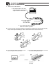
11.4 Options 11.4.1 Shaft Adapters These shaft-shaped adapters are used to install a jig, etc., to the rotating part. Drawing based on combination of RCP2-RTBS/RTBSL Unit model: RCP2-SA-RTS (Unit weight: 0.02 kg) Drawing based on combination of RCP2-RTB/RTBL Unit model: RCP2-SA-RT (Unit weight: 0.04 kg) Drawing based on combination of RCP2-RTBB/RTBBL Unit model: RCP2-SA-RTB (Unit weight: 0.
11.4.2 Table Adapters These table-shaped adapters are used to install a jig, etc., to the rotating part. Drawing based on combination of RCP2-RTB/RTBL Unit model: RCP2-TA-RT (Unit weight: 0.03 kg) Unit model: RCP2-TA-RTS (Unit weight: 0.02 kg) Drawing based on combination of RCP2-RTBB/RTBBL Unit model: RCP2-TA-RTB (Unit weight: 0.06 kg) depth 5 Drawing based on combination of RCP2-RTBS/RTBSL 4-M5, depth 8.6 8-M4, depth 7.5 depth 3 depth 4 4-M3, depth7 depth 7 4-M4, depth7 8-M5, depth 9 depth 1.
RTBS/RTBSL/RTCS/RTCSL table RTB/RTBL/RTCS/RTCL table 6, counterbore depth 3.3 (5 holes are equally distributed) 8-M4 through Design surface R0.2 or less 6.2, counterbore depth 3.3 Design surface RTBB/RTBBL/RTCB/RTCBL table 6SHFL¿FDWLRQV Design surface 7.5, counterbore depth 4.
Change History Revision Date April 2011 March 2012 Description of Revision Seventh edition A page for CE Marking added Eighth edition • P 1 to 7 • P8 Contents added and changed in Safety Guide Caution in Handling added • P 10 to 11 Contents changed in 3. Warranty • P 51 to 54 Warning notes added such as in case the grease got into your eye, immediately go to see the doctor for an appropriate care.
Manual No.: ME3626-9A (March 2013) Head Office: 577-1 Obane Shimizu-KU Shizuoka City Shizuoka 424-0103, Japan TEL +81-54-364-5105 FAX +81-54-364-2589 website: www.iai-robot.co.jp/ Technical Support available in USA, Europe and China Head Office: 2690 W.