ROBO Cylinder Short Type RCP2/RCA Actuator Motor-reversing Specification Operating Manual Fifth Edition Motor-reversing Short Rod Type SRA4R, SRGS4R, SRGD4R IAI America, Inc.
Please Read Before Use Thank you for purchasing our product. This Operation Manual explains the handling methods, structure and maintenance of this product, among others, providing the information you need to know to use the product safely. Before using the product, be sure to read this manual and fully understand the contents explained herein to ensure safe use of the product. The CD or DVD that comes with the product contains Operation Manuals for IAI products.
Table of Contents Safety Guide ························································································································1 Precautions in Handling ·······································································································8 International Standards Compliances ··················································································9 Names of the Parts (or option)················································································
. External Dimensions ···································································································39 7. Warranty ·····················································································································46 6.1 6.2 6.3 6.4 6.5 6.6 6.7 7.1 7.2 7.3 7.4 7.5 7.
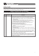
Safety Guide “Safety Guide” has been written to use the machine safely and so prevent personal injury or property damage beforehand. Make sure to read it before the operation of this product. Safety Precautions for Our Products The common safety precautions for the use of any of our robots in each operation. No.
No. 2 2 Operation Description Transportation 3 Storage and Preservation 4 Installation and Start Description Ɣ When carrying a heavy object, do the work with two or more persons or utilize equipment such as crane. Ɣ When the work is carried out with 2 or more persons, make it clear who is to be the leader and who to be the follower(s) and communicate well with each other to ensure the safety of the workers.
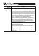
No. 4 Operation Description Installation and Start Description (2) Cable Wiring Ɣ Use our company’s genuine cables for connecting between the actuator and controller, and for the teaching tool. Ɣ Do not scratch on the cable. Do not bend it forcibly. Do not pull it. Do not coil it around. Do not insert it. Do not put any heavy thing on it. Failure to do so may cause a fire, electric shock or malfunction due to leakage or continuity error.
No. 4 5 4 Operation Description Installation and Start Teaching Description (4) Safety Measures Ɣ When the work is carried out with 2 or more persons, make it clear who is to be the leader and who to be the follower(s) and communicate well with each other to ensure the safety of the workers. Ɣ When the product is under operation or in the ready mode, take the safety measures (such as the installation of safety and protection fence) so that nobody can enter the area within the robot’s movable range.
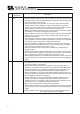
No. 6 7 Operation Description Trial Operation Automatic Operation Description Ɣ When the work is carried out with 2 or more persons, make it clear who is to be the leader and who to be the follower(s) and communicate well with each other to ensure the safety of the workers. Ɣ After the teaching or programming operation, perform the check operation one step by one step and then shift to the automatic operation.
No. 8 9 6 Operation Description Maintenance and Inspection 10 Modification and Dismantle Disposal 11 Other Description Ɣ When the work is carried out with 2 or more persons, make it clear who is to be the leader and who to be the follower(s) and communicate well with each other to ensure the safety of the workers. Ɣ Perform the work out of the safety protection fence, if possible.
Alert Indication The safety precautions are divided into “Danger”, “Warning”, “Caution” and “Notice” according to the warning level, as follows, and described in the operation manual for each model. Level Degree of Danger and Damage Symbol Danger This indicates an imminently hazardous situation which, if the product is not handled correctly, will result in death or serious injury.
Precautions in Handling 1. Ensure use of the product in the specified conditions, environments and ranges. Operation out of the specified conditions could cause a drop in performance or malfunction of the product. 2. Back and forth operation in short distance may wear out the oil film of the grease. If the actuators are moved back and forth continuously over a short distance of 30 mm or less, grease film may run out.
International Standards Compliances This actuator complies with the following overseas standards. Refer to Overseas Standard Compliance Manual (ME0287) for more detailed information.
Names of the Parts (or option) In this Operation Manual, the left and right sides are indicated by looking at the actuator from the motor end, with the actuator placed horizontally, as shown in the figure below.
(2) Motor-reversing short rod type with single guide installed on the right (option) • RCP2-SRGS4R • RCA-SRGS4R Guide bearing Opposite side of the Motor Guide rod Motor side Guide bracket (3) Motor-reversing short rod type with single guide installed on the left (option) • RCP2-SRGS4R • RCA-SRGS4R Guide rod Guide bearing Opposite side of the Motor Motor side Guide bracket 11
(4) Motor-reversing short rod type with single guide installed at the bottom (option) • RCP2-SRGS4R • RCA-SRGS4R Opposite side of the Motor Motor side Guide bracket Guide bearing Guide rod (5) Motor-reversing short rod type with double guides (option) • RCP2-SRGD4R • RCA-SRGD4R Mounting bracket Opposite side of the Motor Guide bracket 12 Guide bearing Guide rod Motor side
1. Specifications Check The standard configuration of this product is comprised of the following products. See the component list for the details of the enclosed components. If you find any fault or missing parts, contact your local IAI distributor. 1.1.1 Parts No. 1 Part Name Actuator Main Body Accessories 2 Motor • Encoder Cable 3 Nut M10 • 1.
[2] RCA 1. Specifications Check No.
1.1.4 How to Read the Model Number [1] RCP2 RCP2 Short Type SRA4R Short Type With Single Guide SRGS4R Short Type With Double Guide SRGD4R I : Incremental 35P : 35 frame 2.5 : 2.5mm 5 : 5mm [1.2.
1. Specifications Check [2] RCA RCP2-SRA4R-I-20-5-20-P1-P-B-** RCA Short Type SRA4R Short Type With Single Guide SRGS4R Short Type With Double Guide SRGD4R I : Incremental 20P : 20W 2.5 : 2.5mm 5 : 5mm [1.2.
1.2 Specification 1.2.1 Speed Type Speed limits [Unit: mm/s] Motor Lead Horizontal/ Min. Type [mm] Vertical speed SRA4R SRGS4R 35P SRGD4R 2.5 5 Horizontal Vertical Horizontal Vertical Stroke [mm] 20 30 40 50 60 70 80 90 100 110 3.12 125 6.25 250 120 130 140 150 160 170 180 190 200 130 140 150 160 170 180 190 200 (Note) The stroke for the brake type is from 70mm. [2] RCA Type Speed limits [Unit: mm/s] Motor Lead Horizontal/ Min.
1.2.2 Maximum Acceleration and Transportable Weight [1] RCP2 1. Specifications Check Due to the specification of the pulse motor, the transportable weight reduces as the speed goes up. Type Motor Type Lead [mm] Horizontal/ Vertical Speed [mm/s] Acceleration/ Deceleration [G] Horizontal 125 0.2 Vertical 125 0.2 Horizontal 250 0.3 Vertical 250 0.2 2.5 SRA4R SRGS4R SRGD4R 35P 5 Horizontal Mount Vertical Mount Lead 2.5mm Lead 5mm Transportable Weight (kg) Lead 2.
1.2.3 Driving System and Position Detector [1] RCP2 SRA4R SRGS4R SRGD4R Motor Type Lead No. of Encoder Pulses Type Diameter Accuracy 800 Rolled I 8mm C10 Ball Screw Type 1. Specifications Check Type 2.5 35P 5 [2] RCA Type Motor Type SRA4R SRGS4R SRGD4R 20W Lead Ball Screw Type No. of Encoder Pulses Type Diameter Accuracy 800 Rolled I 8mm C10 2.5 5 1.2.4 Positioning Accuracy [1] RCP2 Type Lead SRA4R SRGS4R SRGD4R 2.
1.2.5 Rod Non-Rotation Accuracy 1. Specifications Check [1] RCP2 Type Lead [mm] Performance SRA4R 2.5, 5 - SRGS4R 2.5, 5 ±0.05° SRGD4R 2.5, 5 ±0.05° Lead [mm] Performance [2] RCA Type 20 SRA4R 2.5, 5 - SRGS4R 2.5, 5 ±0.05° SRGD4R 2.5, 5 ±0.
1.2.6 Relation Between Current Limit and Pressing Force Perform the pressing operation with RCP2 (stepping motor). 1. Specifications Check RCP2 Pressing Force Lead 2.5mm Lead 5mm Pressing Force (N) Current-Limiting Value (Ratio %) Caution: (1) The relation of the current limit and the pressing force is a reference assuming when the speed is 20mm/s. (2) There will be a little variance in the actual pressing force.
1.2.7 Duty Ratio in Continuous Operation 1. Specifications Check [1] RCP2 Operation can be performed with the duty ratio 100%. Duty ratio is the rate of operation expressed in % that presents the time of the actuator being operated in 1 cycle of operation. [2] RCA Perform an operation with the duty ratio below the allowable range. Caution: If the overload error occurs, try either to reduce the duty by extending the stop time or to reduce the acceleration/deceleration speed.
3) From the load ratio LF and the acceleration/deceleration time ratio tod that were used to figure out the duty ratio, read the duty ratio. e.g.) When the load ratio LF = 80% and the acceleration/deceleration time ratio tod = 80%, the reference for the duty is approximately 75%. LF = 60% Approx. 75% LF = 70% LF = 80% 60 LF = 90% LF = 100% Load factor (%) LF = Less than 50% 80 Reference duty (%) 1.
1.3 Option With Brake (Model No.: B) This is a function to hold the rod so it would not drop when the power or the servo is turned OFF in the condition that the actuator is installed in the vertical orientation. It is to be used to avoid damaging the attached objects by the rod being dropped. 1.3.2 Flange Bracket (Front) (Model No.: FL) This is a metal component for flange to fix the unit on the rod side. RCP2/RCA-SRA4R Model code of single product RCP2-FL-SRA4 34 44.5 4-φ6.6 through 60 75 5.25 0.
1.3.4 Foot brackets 1 (Model No.: FT) It is a metal part to be attached on the bottom of the actuator to affix with screws from top side. 4-φ6.6 through 71 57 20 1. Specifications Check RCP2 / RCA-SRA4R Model code of single product RCP2-FT-SRA4 10 95 105 st+10 1.3.5 Foot brackets 2 (Model No.: FT2 (Attachment to the Right Side), FT2 (Attachment to the Left Side)) This is a foot bracket to fix the actuator unit from with screws. 1.3.6 Low Power Consumption Type (Model No.
1.4 Motor • Encoder Cables [1] RCP2 1. Specifications Check Model number: CB-PCS-MPAƑƑƑ ƑƑƑ indicates the cable length (L) (Example: 030=3m), Max.20m L Controller Side Signal Name Pin No. B1 IA VMM A2 A1 I/A B3 IB VMM B2 A3 I/B NC NC BK + BK LS + LS A+ AB+ BNC VPS VPP GND NC Shield, FG 26 3 2 14 13 16 15 12 11 10 9 8 7 6 5 4 1 (A11) (B11) (A1) (B1) Actuator Side Pin No.
[2] RCA 1. Specifications Check Model number: CB-ACS-MPAƑƑƑ ƑƑƑ indicates the cable length (L) (Example: 030=3m), Max.20m L ( A11) ( B11) ( A1) ( B1) L Controller Side Signal Name Pin No. For ABZ For Serial U V W NC NC NC BK + BK LS + LS A+ AB+ BZ+ Z/PS VCC GND Shield,FG U V W NC NC NC BK + BK LS + LS SD + SD BAT + BAT VCC GND Shield,FG 1 2 3 4 3 2 16 15 18 17 14 13 12 11 10 9 8 7 6 5 1 Actuator Side Signal Name Pin No.
2. Installation 2. Installation 2.1 Transportation [1] Handling of Robot Unless otherwise specified, the actuators are packaged individually. (1) Handling the Packed Unit y Do not damage or drop. The package is not applied with any special treatment that enables it to resist an impact caused by a drop or crash. y Keep the unit in horizontal orientation when placing it on the ground or transporting. Follow the instruction if there is any for the packaging condition. y Do not step or sit on the package.
[2] Handling in Assembled Condition This is the case when the product is delivered from our factory under a condition that it is assembled with other actuators. The combined axes are delivered in a package that the frame is nailed on the lumber base. The rods are fixed so they would not accidently move. The actuators are also fixed so the tip of it would not shake due to the external vibration. (2) How to Handle after Unpackaged y Fix the rod so they would not accidently move during transportation.
2.2 Installation and Storage • Preservation Environment [1] Installation Environment 2. Installation The actuator should be installed in a location other than those specified below. In general, the installation environment should be one in which an operator can work without protective gear. Also provide sufficient work space required for maintenance inspection.
2.3 How to Installation This chapter explains how to install the actuator on your mechanical system. 2.3.1 Installation of the Main Unit 2. Installation Tapped holes are provided on the front face, rear face, right/left side faces and bottom face of the actuator so that the actuator can be installed from any of these five directions. The tapped hole size varies depending on the mounting surface. (Refer to 6, “External Dimensions.
3 Connecting with the Controller 3. Connecting with the Controller For the controller, only the dedicated controller manufactured by our company can be used. Using other controllers may cause a problem such as burning the product, ignition or generating heat. Use the dedicated cable enclosed in the package when connecting the actuator and the controller.
Warning: For wiring, please follow the warnings stated below. When constructing a system as the machinery equipment, pay attention to the wiring and connection of each cable so they are conducted properly. Not following them may cause not only a malfunction such as cable breakage or connection failure, or an operation error, but also electric shock or electric leakage, or may even cause a fire. • Use dedicated cables of IAI indicated in this instruction manual.
• Do not pull the cable with a strong force. 3. Connecting with the Controller • Pay attention not to concentrate the twisting force to one point on a cable. • Do not pinch, drop a heavy object onto or cut the cable. • When a cable is fastened to affix, make sure to have an appropriate force and do not tighten too much. Do not use spiral tube in any position where cables are bent frequently.
Follow the instructions below when using a cable track. • If there is an indication to the cable for the space factor in a cable track, refer to the wiring instruction given by the supplier when storing the cable in the cable track. • Avoid the cables to get twined or twisted in the cable track, and also to have the cables move freely and do not tie them up. (Avoid tension being applied when the cables are bent.) Do not pile up cables. It may cause faster abrasion of the sheaths or cable breakage. 3.
4. Setting of Home Position 4. Setting of Home Position 4.1 Fine-Tuning of Home Position It is approximately 3mm for the distance to stop at the home position after reversing at the mechanical end for home-return operation. If the home-return direction is the same, the home position of the actuator can be fine-tuned by changing the parameter. Follow the instruction below when a fine-tuning is necessary. 1) Perform the home-return operation.
5. Inspection 5.1 Inspection Items and Inspection Schedule Have maintenance inspections following the intervals below. 8 hours per day is assumed as operation condition. Have inspections more frequently if the operation frequency is high for night and day continuous operation, etc. Visual inspection { { { { { Grease supplyNote 1 5.
5.4 Grease Supply 5.4.1 Grease to Apply The actuator is shipped with lithium grease applied to the ball screw. The following dedicated grease is applied to the ball screw prior to the shipment from our factory.Apart from above, there are equivalent sorts of grease sold in the market. Kyodo Yushi 5. Inspection 5.4.2 Multemp LRL No. 3 Grease supply When performing maintenance, add grease from the greasing port using a spray-type lithium grease to lubricate the ball screw.
50 Secure at least 100 0 0 0 0 0 1 1 1 1 2 3 20 124.5 84 62 30 30 134.5 94 72 40 40 144.5 104 82 50 50 154.5 114 92 60 60 164.5 124 102 70 70 174.5 134 112 30 80 184.5 144 122 40 90 194.5 154 132 50 100 204.5 164 142 60 150 254.5 214 192 60 200 304.5 264 242 60 B D A C L 45 34 14 95 st 39 RCA 1.64 1.66 1.59 1.61 1.33 1.35 1.27 1.30 1.27 1.29 1.21 1.23 1.21 1.23 1.15 1.17 1.14 1.16 1.09 1.11 1.08 1.10 1.03 1.05 1.02 1.04 0.96 0.98 0.96 0.98 0.90 0.92 0.89 0.91 0.
0 0 0 0 0 1 1 1 1 2 3 30 136.5 94 72 40 40 146.5 104 82 50 50 156.5 114 92 60 60 166.5 124 102 70 70 176.5 134 112 30 80 186.5 144 122 40 90 196.5 154 132 50 100 206.5 164 142 60 150 256.5 214 192 60 200 306.5 264 242 60 B 20 126.5 84 62 30 A D L C st RCP2 RCA 2.09 2.11 2.03 2.05 1.75 1.77 1.69 1.71 1.68 1.70 1.62 1.64 1.61 1.63 1.56 1.58 1.54 1.56 1.49 1.51 1.48 1.50 1.42 1.44 1.41 1.43 1.35 1.37 1.34 1.36 1.28 1.30 1.27 1.29 1.21 1.23 1.20 1.22 1.15 1.
0 0 0 1 1 1 1 2 40 146.5 104 82 50 50 156.5 114 92 60 60 166.5 124 102 70 70 176.5 134 112 30 80 186.5 144 122 40 90 196.5 154 132 50 100 206.5 164 142 60 150 256.5 214 192 60 3 0 30 136.5 94 72 40 200 306.5 264 242 60 0 B 20 126.5 84 62 30 A D L C st RCA 2.09 2.11 2.03 2.05 1.75 1.77 1.69 1.71 1.68 1.70 1.62 1.64 1.61 1.63 1.56 1.58 1.54 1.56 1.49 1.51 1.48 1.50 1.42 1.44 1.41 1.43 1.35 1.37 1.34 1.36 1.28 1.30 1.27 1.29 1.21 1.23 1.20 1.22 1.15 1.
0 0 0 0 0 1 1 1 1 2 3 30 136.5 94 72 40 40 146.5 104 82 50 50 156.5 114 92 60 60 166.5 124 102 70 70 176.5 134 112 30 80 186.5 144 122 40 90 196.5 154 132 50 100 206.5 164 142 60 150 256.5 214 192 60 200 306.5 264 242 60 B 20 126.5 84 62 30 A D L C st RCA 2.09 2.11 2.03 2.05 1.75 1.77 1.69 1.71 1.68 1.70 1.62 1.64 1.61 1.63 1.56 1.58 1.54 1.56 1.49 1.51 1.48 1.50 1.42 1.44 1.41 1.43 1.35 1.37 1.34 1.36 1.28 1.30 1.27 1.29 1.21 1.23 1.20 1.22 1.15 1.
0 0 0 1 1 1 1 2 40 146.5 104 82 50 50 156.5 114 92 60 60 166.5 124 102 70 70 176.5 134 112 30 80 186.5 144 122 40 90 196.5 154 132 50 100 206.5 164 142 60 150 256.5 214 192 60 3 0 30 136.5 94 72 40 200 306.5 264 242 60 0 B 20 126.5 84 62 30 A D L C st RCA 2.44 2.46 2.38 2.40 2.07 2.09 2.01 2.03 1.99 2.01 1.94 1.96 1.92 1.94 1.86 1.88 1.84 1.86 1.79 1.81 1.77 1.79 1.71 1.73 1.70 1.72 1.64 1.66 1.62 1.64 1.56 1.58 1.55 1.57 1.49 1.51 1.47 1.49 1.42 1.
6.6 Flange Bracket (option) installed 5.25 6. External Dimensions 60 75 0.25 34 44.5 4-φ6.6 through 10 (40.5) Datail view when flange bracket is installed (at the front) Datail view when flange bracket is installed (at the rear) 44 34 75 44.5 60 0.25 10 5.25 4-φ6.
6.7 Foot Bracket (option) installed 4-φ6.6 through 121 107 20 6. External Dimensions 10 st+10 55 Detail view when foot brackets are installed (on the right or the left) (Foot brackets can be installed on either the right side or the left side.) 4-φ6.
7. Warranty 7.1 Warranty Period One of the following periods, whichever is shorter: y 18 months after shipment from our company y 12 months after delivery to the specified location y 2,500 hours of operation 7.2 Scope of the Warranty 7. Warranty Our products are covered by warranty when all of the following conditions are met.
7.4 Limited Liability (1) We shall assume no liability for any special damage, consequential loss or passive loss such as a loss of expected profit arising from or in connection with our product. (2) We shall not be liable for any program or control method created by the customer to operate our product or for the result of such program or control method. 7.5 Conditions of Conformance with Applicable Standards/Regulations, Etc., and Applications 7.
Change History Revision Date Change History April 2011 48 Description of Revision Third edition A page for CE Marking added September 2011 Fourth edition Change in pressing force graph in Pg.
Manual No.: ME3665-5A (November 2012) Head Office: 577-1 Obane Shimizu-KU Shizuoka City Shizuoka 424-0103, Japan TEL +81-54-364-5105 FAX +81-54-364-2589 website: www.iai-robot.co.jp/ Technical Support available in USA, Europe and China Head Office: 2690 W.