ROBO Cylinder RCP2W Actuator Slider, Dust-proof/Splash-proof Type Operating Manual Sixth Edition RCP2W-SA16C IAI America, Inc.
Please Read Before Use Thank you for purchasing our product. This Operating Manual explains the handling methods, structure and maintenance of this product, among others, providing the information you need to know to use the product safely. Before using the product, be sure to read this manual and fully understand the contents explained herein to ensure safe use of the product. The CD or DVD that comes with the product contains Operating Manuals for IAI products.
Table of Contents Safety Guide...................................................................................................................................1 Caution in Handling ........................................................................................................................8 International Standards Compliances ...........................................................................................10 Names of the Parts..........................................................
7. Life .........................................................................................................................................34 8. Warranty.................................................................................................................................35 8.1 Warranty Period ..............................................................................................................35 8.2 Scope of the Warranty ..............................................................
Safety Guide “Safety Guide” has been written to use the machine safely and so prevent personal injury or property damage beforehand. Make sure to read it 1before the operation of this product. Safety Precautions for Our Products The common safety precautions for the use of any of our robots in each operation. No.
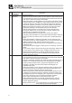
No. 2 2 Operation Description Transportation 3 Storage and Preservation 4 Installation and Start Description Ɣ When carrying a heavy object, do the work with two or more persons or utilize equipment such as crane. Ɣ When the work is carried out with 2 or more persons, make it clear who is to be the leader and who to be the follower(s) and communicate well with each other to ensure the safety of the workers.
No. 4 Operation Description Installation and Start Description (2) Cable Wiring Ɣ Use our company’s genuine cables for connecting between the actuator and controller, and for the teaching tool. Ɣ Do not scratch on the cable. Do not bend it forcibly. Do not pull it. Do not coil it around. Do not insert it. Do not put any heavy thing on it. Failure to do so may cause a fire, electric shock or malfunction due to leakage or continuity error.
No. 4 5 4 Operation Description Installation and Start Teaching Description (4) Safety Measures Ɣ When the work is carried out with 2 or more persons, make it clear who is to be the leader and who to be the follower(s) and communicate well with each other to ensure the safety of the workers. Ɣ When the product is under operation or in the ready mode, take the safety measures (such as the installation of safety and protection fence) so that nobody can enter the area within the robot’s movable range.
No. 6 7 Operation Description Trial Operation Automatic Operation Description Ɣ When the work is carried out with 2 or more persons, make it clear who is to be the leader and who to be the follower(s) and communicate well with each other to ensure the safety of the workers. Ɣ After the teaching or programming operation, perform the check operation one step by one step and then shift to the automatic operation.
No. 8 9 6 Operation Description Maintenance and Inspection 10 Modification and Dismantle Disposal 11 Other Description Ɣ When the work is carried out with 2 or more persons, make it clear who is to be the leader and who to be the follower(s) and communicate well with each other to ensure the safety of the workers. Ɣ Perform the work out of the safety protection fence, if possible.
Alert Indication The safety precautions are divided into “Danger”, “Warning”, “Caution” and “Notice” according to the warning level, as follows, and described in the Operating Manual for each model. Level Degree of Danger and Damage Danger This indicates an imminently hazardous situation which, if the product is not handled correctly, will result in death or serious injury.
Caution in Handling 1. Ensure use of the product in the specified conditions, environments and ranges. Not keeping this may cause a drop in the performance or even a malfunction of the product. 2. Do not attempt to handle or operate the product in a way that is no described in the Operating manual. 3. Use the products of IAI for the wiring between an actuator and a controller. 4. Do not set speeds and accelerations/decelerations equal to or greater than the respective ratings.
10. Do not perform a pressing operation. Also, do not apply an excessive impact on the slider such as by hitting it with a hammer, etc. Since the ball screw nut and the slider are joined together via a pipe material by magnetic force, the ball screw and slider may get separated out of the magnetic joint if an excessive impact is applied to them, resulting in such a problem as the actuator to malfunction. 11.
International Standards Compliances This actuator complies with the following overseas standards. Refer to Overseas Standard Compliance Manual (ME0287) for more detailed information.
Names of the Parts In this Operating Manual, the left and right sides are indicated by looking at the actuator from the motor end, with the actuator placed horizontally, as shown in the figure below.
12
Specifications Check 1.1 Checking the Product The standard configuration of this product is comprised of the following parts. See the component list for the details of the enclosed components. If you find any fault or missing parts, contact your local IAI distributor. 1.1.1 Parts No. 1 Name Actuator Model number Refer to “How to Read the Model Nameplate” and “How to Read the Model Number.
1.1.4 How to Read the Model Number 1. Specifications Check RCP2W㧙SA16C㧙I㧙86P㧙8㧙100㧙P2㧙S㧙NM㧙 Identification for IAI use only(Note1) Series CO : With Cover Type NM : Reversed-Home Type I : Incremental 86P : Pulse Motor 56Ƒ High Output 4 : 4mm 8 : 8mm N : None P : 1m S : 3m M : 5m XƑƑ : Length specification (Example: X07=7m) RƑƑ : Robot cable (Example: R05=5m) P2 : PCON-CA PCON-CFA [Refer to 1.
1.2 Specification 1.2.1 Speed 86P 1.2.2 1. Specifications Check Motor Type Speed limits (Unit: mm/s) Minimum Lead [mm] Speed 8 4 Stroke [mm] 50 to 600 [Every 50mm ] 180 133 Maximum Acceleration and Load Capacity The Maximum Acceleration is 0.2G Motor Type Lead [mm] Load Capacity [kg] 8 25 86P 4 35 ■Correlation diagram of speed and load capacity For RCP2 Series, the load capacity will reduce if the speed increases due to the characteristics of the pulse motor.
1. Specifications Check 1.2.3 Driving System • Position Detector Motor Type Lead 86P 8 4 1.2.4 No. of Encoder Pulses Type Diameter Accuracy 800 Rolled I12 C10 Ball Screw Type Positioning repeatability ±0.08mm * The values shown above are the accuracy at the delivery from the factory. It does not include the consideration of time-dependent change as it is used. 1.2.5 Lost motion 0.7mm or less * The values shown above are the accuracy at the delivery from the factory.
1.2.6 Load Moments of the Actuator Allowable Overhang Load Length (L) 1. Specifications Check Allowable Static Load Moment [N•m (Kgf•m)] 20 (2.04) Ma direction: 200, Mb or Mc direction (Note 1) Mb/Mc directions Ma direction Note 1 Avoid applying moment load to Mb or Mc direction during an operation. 1.2.7 Duty Ratio of Continuous Operation During continuous operation, the actuator generates frictional heat due to sliding of the pipe over the wear ring.
1.3 1. Specifications Check 1.3.1 Options With Cover Type (Model: CO) It is a cover to protect the guide part and slider part. [Refer to 5. External Dimensions] 1.3.2 Reversed-Home Type (Model: NM) The home position is normally set on the motor side, however, the home direction can be set opposite by option if a reversed type is required due to such a reason as the layout of the system.
1.4 Motor • Encoder Cables 1.4.1 Motor Cables 1. Specifications Check * The motor cable is a robot cable as standard. CB-RCP2-MAƑƑƑ (20) C N 1 CN3 (Front View) (14) (15) (14) (28) (20) (φ8) (8) (Front View) L Controller Side Mechanical Side Min. Bending Radius = 50mm or more (Movable Use) Electric Wire Color Signal Name Orange A Gray VMM I-1318119-3 White B Yellow A (AMP) Pink VMM Yellow (Green) B Width 1.4.2 Pin No. Pin Signal Electric Width No.
2. Installation 2. Installation 2.1 Transportation [1] Handling of the Robot Unless otherwise specified, the actuators are packaged individually. (1) Handling the Packed Unit y Do not damage or drop. The package is not applied with any special treatment that enables it to resist an impact caused by a drop or crash. y An operator should never attempt to carry a heavy package on their own. Also, use an appropriate way for transportation.
[2] Handling in the Assembled Condition This is the case when the product is delivered from our factory under a condition that it is assembled with other actuators. The combined axes are delivered in a package that the frame is nailed on the lumber base. The sliders are fixed so they would not accidently move. The actuators are also fixed so the tip of it would not shake due to the external vibration.
2.2 Installation and Storage • Preservation Environment [1] Installation Environment 2. Installation The actuator should be installed in a location other than those specified below. In general, the installation environment should be one in which an operator can work without protective gear. Also provide sufficient work space required for maintenance inspection.
2.3 How to Install This chapter explains how to install the actuator on your mechanical system. General Rules on Installation 2. Installation 2.3.1 Follow the information below when installing the actuator, as a rule. Do pay attention to these items (except with custom-order models).
2. Installation 2.3.2 Installation of the Main Unit • The base plates on both ends of the actuator have through holes. Use these holes when installing the actuator. • For the platform to install the actuator on, ensure the structure has enough stiffness to avoid vibration being generated. • The surface where the actuator will be mounted should be machined or be equally level and the flatness tolerance between the actuator and the table should be within 0.05mm/m.
2.3.3 Attachment of the Transported Object • There are tapped holes on the top face of the slider. Affix the transported object here. • There are two reamed holes on the top face of the slider. When repeatability in re-attaching is required after it is detached, utilize these reamed holes. Also, use only one reamed hole on the slider when fine-tuning such as perpendicularity is required. 2.
3. Connecting with the Controller 3. Connecting with the Controller For the connection of an actuator to the controller, apply an IAI dedicated controller and dedicated connection cable. This section, describes how to connect with a single axis type. • If the dedicated connection cable cannot be secured, reduce the load on the cable by allowing it to deflect only by the weight of the cable or wire it in a self–standing cable hose, etc., having a large radius.
Warning: For wiring, please follow the warnings stated below. When constructing a system as the machinery equipment, pay attention to the wiring and connection of each cable so they are conducted properly. Not following them may cause not only a malfunction such as cable breakage or connection failure, or an operation error, but also electric shock or electric leakage, or may even cause a fire. 3. Connecting with the Controller • Use dedicated cables of IAI indicated in this instruction manual.
3. Connecting with the Controller • Do not pull the cable with a strong force. • Pay attention not to concentrate the twisting force to one point on a cable. • Do not pinch, drop a heavy object onto or cut the cable. • When a cable is fastened to affix, make sure to have an appropriate force and do not tighten too much. Do not use spiral tube in any position where cables are bent frequently.
Follow the instructions below when using a cable track. • If there is an indication to the cable for the space factor in a cable track, refer to the wiring instruction given by the supplier when storing the cable in the cable track. 3. Connecting with the Controller • Avoid getting cables twined or twisted in the cable track, and also having the cables move freely and do not tie them up. (Avoid tension being applied when the cables are bent.) Do not pile up cables.
4. Maintenance Inspection 4.1 Inspection Items and Schedule 4. Maintenance Inspection Follow the maintenance inspection schedule below. It is assumed that the equipment is operating 8 hours per day. If the equipment is running continuously night and day or otherwise running at a high operating rate, inspect more often as needed.
4.3.2 How to apply the grease [How to Add Grease] If the actuator has a screw cover, remove the cover. Clean the surface of the slider rod, and apply grease over the entire surface using your finger. To reach inaccessible areas of the slider, turn on the power and move the slider until the applicable areas are exposed. Then, turn off the power and apply grease.
5. External Dimensions 5.1 Without cover specification (2m) L 15 20 15 20 65 4-M8 Depth 20 Cable Joint Connector φ90 80 5. External Dimensions A 65 130 90 115 4-9 Drilled Hole, φ14 Counterbore, Depth 8.5 155 A B Actuator cable 2-φ8H7 Depth 10 25 52 4 S(Stroke) HOME SE 53 5 25 125 30 ME 105 100 ME 130 4.3 ±0.2 7.3 ±0.2 Base Plate (material A50 52P) 8 6.
6. How to use the home mark Please affix these marks to the actuator as home markers as needed. Contents of sticker Home mark sticker × 1 sheet 6. How to use the home mark Home mark scale × 4 Home mark × 4 (Scale: 1 mm graduation mark, 10 mm width) • Peel off the marks from the base sheet. Note 1. Every mark has sticky back. 2. Remove smear and stain from the surface. 3. Avoid label or nameplate as a marking location.
7. Life 7. Life The product life is assumed to be 5,000km (reference) under the condition that it runs with maximum load capacity and maximum acceleration/deceleration.
8. Warranty 8.1 Warranty Period One of the following periods, whichever is shorter: y 18 months after shipment from IAI y 12 months after delivery to the specified location y 2,500 hours of operation 8.
8.5 Conditions of Conformance with Applicable Standards/Regulations, Etc., and Applications 8. Warranty (1) If our product is combined with another product or any system, device, etc., used by the customer, the customer must first check the applicable standards, regulations and/or rules. The customer is also responsible for confirming that such combination with our product conforms to the applicable standards, etc.
Change History Revision Date April 2011 March 2012 Description of Revision Fourth edition A page for CE Marking added Fifth edition P1 to 7: P8: P10 to 11: P23: P24: February 2013 Contents added and changed in Safety Guide Caution in Handling added Contents changed in 3. Warranty Warning notes added such as in case the grease got into your eye, immediately go to see the doctor for an appropriate care.
Manual No.: ME3651-6A (February 2013) Head Office: 577-1 Obane Shimizu-KU Shizuoka City Shizuoka 424-0103, Japan TEL +81-54-364-5105 FAX +81-54-364-2589 website: www.iai-robot.co.jp/ Technical Support available in USA, Europe and China Head Office: 2690 W.