RCS Series ROBO Cylinder Controller RCS-E Type Operation Manual Seventh Edition
Please Read Before Use Thank you for purchasing our product. This Operation Manual explains the handling methods, structure and maintenance of this product, among others, providing the information you need to know to use the product safely. Before using the product, be sure to read this manual and fully understand the contents explained herein to ensure safe use of the product. The CD that comes with the product contains operation manuals for IAI products.
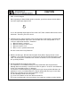
CAUTION (1) Hold · Servo ON Signal When operating the RCS (ROBO cylinder) controller, you will need to turn ON the Hold & Servo ON signal Input Signal of PIO. In case the Hold Stop Input Signal of PIO remains OFF, RCS controller will not move due to hold status. Therefore, please be careful. (2) Position 0 may be output regardless of the actual position. At the timings specified below, the positioning completion signal turns ON no matter where the actual position is.
Table of Contents Safety Guide ....................................................................................................... 1 1. Overview........................................................................................................ 1 1.1 1.2 1.3 1.4 1.5 1.6 Forward .....................................................................................................................................................1 How to Read Model Number ................................................
5. Parameters .................................................................................................. 61 5.1 Parameter Classification .........................................................................................................................61 5.2 Parameter List .........................................................................................................................................61 5.3 Parameter Settings..............................................................
Safety Guide This “Safety Guide” is intended to ensure the correct use of this product and prevent dangers and property damage. Be sure to read this section before using your product. Regulations and Standards Governing Industrial Robots Safety measures on mechanical devices are generally classified into four categories under the International Industrial Standard ISO/DIS 12100, “Safety of machinery,” as follows: Safety measures Inherent safety design Protective guards --- Safety fence, etc.
Requirements for Industrial Robots under Ordinance on Industrial Safety and Health Work area Outside movement range Inside movement range Pre-2 Work condition During automatic operation Cutoff of drive source Measure Signs for starting operation Installation of railings, enclosures, etc. Cut off (including Sign, etc., indicating that work is in stopping of operation) progress Preparation of work rules Measures to enable immediate During stopping of operation teaching, etc. Sign, etc.
Applicable Modes of IAI’s Industrial Robot Machines meeting the following conditions are not classified as industrial robots according to Notice of Ministry of Labor No. 51 and Notice of Ministry of Labor/Labor Standards Office Director (Ki-Hatsu No.
Notes on Safety of Our Products Common items you should note when performing each task on any IAI robot are explained below. No. Task 1 Model selection 2 3 4 Note This product is not planned or designed for uses requiring high degrees of safety. Accordingly, it cannot be used to sustain or support life and must not be used in the following applications: [1]Medical devices relating to maintenance, management, etc.
No. Task 4 Installation/ startup 5 Teaching Note (2) Wiring the cables Use IAI’s genuine cables to connect the actuator and controller or connect a teaching tool, etc. Do not damage, forcibly bend, pull, loop round an object or pinch the cables or place heavy articles on top. Current leak or poor electrical continuity may occur, resulting in fire, electric shock or malfunction. Wire the product correctly after turning off the power.
No. Task 6 Confirmation operation 7 Automatic operation 8 Maintenance/ inspection 9 Modification 10 Disposal Pre-6 Note When releasing the brake of the vertically installed actuator, be careful not to let the actuator drop due to its dead weight, causing pinched hands or damaged load, etc. * Safety fences --- Indicate the movement range if safety fences are not provided. After teaching or programming, carry out step-by-step confirmation operation before switching to automatic operation.
Indication of Cautionary Information The operation manual for each model denotes safety precautions under “Danger,” “Warning,” “Caution” and “Note,” as specified below. Level Degree of danger/loss Symbol Danger Failure to observe the instruction will result in an imminent danger leading to death or serious injury. Danger Warning Failure to observe the instruction may result in death or serious injury. Warning Caution Failure to observe the instruction may result in injury or property damage.
1. Overview 1.1 Forward Thank you very much for purchasing the RCS controller. This manual explains the features of this machine and its operating procedures. Without knowing beforehand how to correctly use or operate the controller, not only will the user be unable to take full advantage of all the functions built into this product but the user might also, inadvertently cause damage to the robot or shorten its life.
1.
1.3 Safety Precautions Please read the following information carefully in order to gain an understanding of safety precautions. This product was developed as components for driving automated equipment and is designed not to produce greater torque or speed than is necessary. However, strictly observe the following items to prevent any accidents from occurring. 1. As a rule, any handling or operating methods not described in this manual should be viewed as things that should not be attempted.
1.4 Warranty Period and Scope of Warranty The RCS controller undergoes stringent testing before it is shipped from our factory. IAI provides the following warranty: 1. Warranty Period The warranty period expires upon elapse of one of the following periods, whichever occurs first. 18 months after the shipment from IAI 12 months after delivery to the location specified by the user. 2.
1.5 Setting Environment and Noise Measures Please be careful for controller setting environment 1.5.1 Installation Environment This controller can be used in an environment of pollution degree 2*1 or equivalent. *1 Pollution degree 2: Normally only nonconductive pollution occurs. Temporary conductivity caused by condensation is to be expected. (EN60947-5-1) (1) Do NOT block the air vents of your controller when installing your IA system.
1.5.3 Noise Elimination Measures and Grounding (1) Noise Elimination Grounding 1. Directly screw the main body to the metal box. 24-V controller Use as thick a cable as practically possible and wire it over the shortest possible distance. [2] If the controller cannot be screwed onto the frame, connect it to the frame as shown in the figure at left. Metal frame [3] Precautions regarding wiring method Use a twisted cable for connection to the 24-VDC external power supply.
(2) Noise sources and elimination Among the numerous noise sources, solenoid valves, magnet switches and relays are of particular concern when building a system. Noise from these sources can be eliminated by implementing the measures specified below. [1] AC solenoid valves, magnet switches and relays Measure: Install a surge absorber in parallel with the coil. Point Install a surge absorber to each coil over a minimum wiring length.
1.6 Heat Radiation and Installation Design the control panel size, controller layout and cooling method in such a way that the temperature around the controller will not exceed 40C. Install the controller vertically on a wall, as shown below. Since cooling is provided by way of natural convection, always observe this installation direction and provide a minimum clearance of 50 mm above and below the controller to ensure sufficient natural airflows.
2. Specification 2.1 Base Specifications Item Specification 24 VDC 10% Supply voltage Type RA35 RA45, F45 RB75 (60 W) SA4, SA5 SA6 Supply current [A] Rating Maximum motor output Surrounding air temperature/humidity Surrrounding environment Weight Protective functions LED indicators DI/DO interface 8 dedicated input ports Input/output 10 dedicated output ports Peak 1.8 4.3 2.4 6.0 3.9 1.2 3.7 1.4 3.
2.1.1 Backup Battery (Absolute Specification) (1) Battery Specification Item Description Type Lithium battery Manufacturer Toshiba Battery Co., Ltd. Model number Nominal voltage Rated capacity ER3VP 3.6 V 2000 mAh Weight Approx. 8.5 g Approx. 20,000 hours (at a surrounding air temperature of 20C). Battery retention time Note 1) Note 1) Approx. 100 A of current is consumed while data is backed up by the absolute data backup battery (as opposed to approx.
2.2 2.2.1 Names and Functions of Parts Names [8] LED indicators [1] Motor connector (M) [2] Brake release switch (BK) (option) [9] Encoder/brake connector [3] SIO connector (SIO) [4] Port switch (PORT) [5] Main communication port connector [10] PIO connector (PIO) [6] Regenerative resistor connector (RB) [11] Piano switches [7] Power/emergency-stop terminal block 2.2.2 Functions [1] Motor connector (MBK) A connector for the actuator’s motor power cable.
[5] Main communication port connector (PORT IN) A connector for receiving the communication cable from a dedicated teaching pendant or external equipment. It also receives a controller link cable when two or more axes are connected. [6] Regenerative resistor connector (RB) A connector for regenerative discharge resistor. The controller will come with a regenerative resistor if the specified actuator capacity is 30 W or above.
Piano switches 1 to 4 --- Address switches Use these switches to set the address of the applicable actuator if two or more axes are connected to the SIO connector. A desired address between 0 to 15 can be set. (The factory setting is OFF for all of switch Nos. 1 to 4. This setting represents a condition where only one axis is used.) Use these switches to set a desired address for each controller. Make sure no address is duplicated among the controllers.
2.2.3 Pin Assignments of the Communication Ports Pin assignments of the SIO connector Pin No. 1 2 3 4 5 6 Signal name (+5V) SGA GND SGB GND (+5V) Function (5-VDC power output) or (preliminary signal terminal) Positive logic side of the line transceiver I/O Communication ground Negative logic side of the line transceiver I/O Communication ground 5-VDC power output Pin assignments of the main communication port Pin No.
Encoder/brake connector [JST S11B-XASK-1] Pin No. 1 2 Signal name EN A+ EN B+ Encoder A+ Encoder B+ Connected wire 3 EN Z+ Encoder Z+ 4 5 6 7 8 9 10 11 EN Z– SD+ SD– EN 5V EN GND BK N BK P FG Encoder ZEncoder SD+ Encoder SDEncoder 5V+ Encoder COMBrakeBrake+ Shield Power/emergency-stop terminal block [Sato ML-800S IH (4P)] Signal name Connected wire [2] [1] 24 V N These terminals are connected to the emergency stop circuit. 24 V is output to [1].
2.
2.4 Connection Method 2.4.1 Standard Type Teaching pendant Optional Cable length: 5 m ROBO Cylinder The cables are optional. Host system Supplied flat cable Cable length: 2 m PC External unit RCB-105-2 (2 m) RCB-105-5 (5 m) PC software Optional EMG switch 24-VDC power supply Do not insert/remove the connectors when the power is on, except for the main communication port connector (PORT IN).
2.4.2 Absolute Specification ROBO Cylinder The absolute specification cannot be used with a standard actuator. The cables are optional. Other connections are the same as those of the standard type.
2.5 2.5.1 Supplied Cable I/O Flat Cable Flat cable 2.5.2 NO. Signal Color NO.
2.5.3 Encoder Extension Cable Actuator end Controller end Cable color Signal abbriviation Pin No. Pin No. Signal abbriviation Cable color Pink Pink White White Orange/white Green/white Blue Orange/white Orange Green/white Purple Blue/red Gray Ground Red Blue Ground Orange Black Cable color Signal abbriviation Pin No. Yellow Purple Blue/red Ground and braided shield wires Gray Red Plug housing: SMP-02V-BC (JST) Socket contact (gold plated): SHF-001T-0.
2.6 Wiring 2.6.1 Wiring for Power Supply/Emergency Stop Power/emergency-stop terminal block * The two EMG terminals are contact-b inputs used for connecting an emergency-stop switch. The controller is shipped with these terminals shorted, so that an emergency stop will not be actuated. Note: When performing power connection, make sure the following specifications for power cable, etc., are satisfied. Single wire --- 1.0 (AWG18) Stranded wire --- 0.75 mm2 (AWG18) Single wire --- 0.4 (AWG26) to 1.
2.6.
2.6.3 PIO Interface A PIO interface list is given below. The PIO cable is a flat cable with no connector attached on the end connected to the external equipment. PIO connector (26 pins) Pin No.
[1] Command position Relationship of input pin numbers and selected position numbers (4-bit binary) One of 16 positions from 0 to 15 can be input/selected. 1: ON Pin No.
[7] Home return completion This signal will turn ON when the initial home return is completed after a power connection. Thereafter, an alarm generated and this signal will remain ON until the power is turned off. It will not turn OFF following an emergency-stop signal input. If the home return completion signal is OFF, it means home return will be performed before the next movement operation.
2.6.4 Non-isolated External I/O Specification Input Part Item Specification Number of inputs 8 points Input voltage 24 VDC 10% Input current 7 mA/1 circuit ON voltage --- 18 V min. OFF voltage --- 6 V max. Not isolated Operation voltage Isolation method Output Part There are two specifications for the output part, namely Group 1 and Group 2.
I/O Circuits Noise filter Power Internal power supply Pin No.
3. Data Entry This controller doesn’t use command words, so there is no need to create a program. All you need is to enter position data in the position-data table, and the actuator will move to the specified position. Position data consists of number (No.), position (Position), speed (Speed), acceleration/deceleration (ACC), push (Push), positioning band (Pos. band), and acceleration only MAX (ACC MAX). The description in parentheses is as displayed on the teaching pendant.
3.1 Description of Position-Data Table (1) No. Indicate the position data number. To enter an incremental movement, press the minus key in this column. On the teaching pendant, a “=” will be displayed between the number and position columns. The minus key need not be pressed in the absolute mode. (2) Position (Position) Enter the target position to move the actuator to, in [mm]. Absolute mode: Enter the distance to the target actuator position from the home. Negative values cannot be entered.
Select the positioning mode or push & hold mode. The default value is “0.” 0: Positioning mode (= Normal operation) Other than 0: Push & hold mode [%] In the push & hold mode, enter the current-limiting value to be applied to the servo motor while the load is being pushed. With the RCS, set the current-limiting value to approx. 70%. The controller will not operate properly if this value is 30% or below.
(7) Acceleration only MAX (ACC MAX) Select the specified acceleration or maximum acceleration by entering “0” or “1.” The default value is “0.” 0: Specified acceleration --- The value entered in (4) becomes the actual acceleration/deceleration. 1: Maximum acceleration --- The maximum acceleration set according to the load is used. The deceleration conforms to the value entered in (4).
3.1.1 Push Force at Standstill In the push & hold mode, enter a current-limiting value (%) in the position-data table under “Push.” With the RCS, use a push force at standstill corresponding to a current-limiting value of approx. 70%. The push force at standstill can be increased or decreased by increasing or decreasing the current-limiting value. However, take note that the controller will not operate properly if the current-limiting value is 30% or below.
3.2 Explanation of Modes Positioning Mode Push = 0 Position complete signal Completed position number Moving OFF Output Speed 3.2.1 (1) The position complete output will turn ON and moving output will turn OFF at a position preceding the target position by the positioning band. A completed position number signal will be output at the same time. Moving distance Positioning band 3.2.
(2) Load was not contacted (missed) Speed Completed position number Moving OFF Output Moving distance Positioning band (1) After reaching the target position, the actuator will move at low speed. Even after contacting the load, the actuator will move to the end of the positioning band if the servo motor current is yet to reach the current-limiting value. The position complete output will not turn ON even when the end of the positioning band is reached.
Speed (4) Positioning band was entered with a wrong sign If the positioning band is entered with a wrong sign, the position will deviate by twice the positioning band, as shown to the left, so exercise due caution. Moving distance Positioning Positioning band band 3.2.3 Speed Change during Movement Speed control involving multiple speed levels is possible in a single operation. The actuator speed can be decreased or increased at a certain point during movement.
3.2.5 Pause This signal can be used to stop the actuator in case of emergency. The movement of the actuator can be paused via an external input signal (pause). For safety reasons, this signal is provided as a contact-b input (based on the negative logic). The actuator will decelerate to a stop when the pause input is turned OFF, and resume movement when the pause input is turned ON.
3.2.7 Home Return With the standard specification, home return must be performed after the power has been input or an encoder open or CPU error alarm has been reset. Selecting a position number and then initiating a start will cause the controller to automatically perform home return before commencing the subsequent operation. Once home return is complete, the home return completion output will turn ON (standard specification). Home return alone cannot be performed using PIO.
4. Using the Controller 4.1 How to Start (Standard Type) (Refer to 4.2, “How to Execute An Absolute Reset,” for the absolute specification.) (1) Confirm that both Nos. 5 and 6 of piano switch are set to OFF. If these switches are set to ON, tilt them back to the OFF positions. (2) Connect the motor/brake cables and encoder cable to the controller. (3) Connect the host PLC to the PIO connector using the supplied flat cable.
4.2 How to Execute Absolute Reset (Absolute Specification) Note) With the absolute specification, 0E5 (an encoder receive error) will occur when the power is turned on for the first time after the battery or PG cable was disconnected. This does not indicate fault. If this error occurs, execute an absolute reset by following the specified procedure. The specific method to execute an absolute reset will vary depending on the controller version.
How to Execute an Absolute Reset on a a SERIAL No. J* or Earlier [1] [2] [3] Connect the motor and encoder/brake cables to the controller. Connect the host PLC to the PIO connector using the supplied flat cable. If two or more axes are connected, set the address using SW1 on the controller. For details, refer to “Names and Functions of Parts.” [4] Move the actuator slider or rod to a position where it is in contact with the mechanical end on the home side. [5] Turn ON piano switch (SW) No.
4.3 Movement after Power On (Standard Type) Example of use in operation) After the power is turned on, move the actuator to the position 150 mm from the home at a speed of 200 mm/sec. Position-data table (Field(s) within thick line must be entered.) No. Position 0 1 Speed 0 150 100 200 Acceleration/ deceleration 0.3 0.3 Push Positioning band 0 0 0.1 0.
Power ON Servo ON Command position Position 1 Start Note Pause Position complete Alarm Emergency stop Completed position Position 1 * Home return completion Speed Moving Positioning band *Actuator movement Time The position complete output will turn ON when the controller becomes ready following the power ON. (The position complete output will not turn ON if the servo ON input is OFF.) To check if the controller is ready, always check if the position complete output is ON.
4.4 Positioning Mode (Back and Forth Movement between Two Points) Example of use in operation) The actuator moves back and forth between two positions. The position 250 mm from the home is set as position 1, and the position 100 mm from the home is set as position 2. The travel speed to position 1 is set as 200 mm/sec, and to position 2 is set as 100 mm/sec. RCS controller PIO Signal name Reference flow Category [13] [10] [5] [2] Start [1] [1] Select/enter command position 1.
Position-data table (Field(s) within thick line must be entered.) No. Position Speed 0 * * Acceleration/ deceleration * 1 250 200 2 100 100 Push Positioning band * * Acceleration only MAX * 0.3 0 0.1 0 0.3 0 0.
4.5 Push & Hold Mode Example of use in operation) The actuator is caused to move back and forth in the push & hold mode and positioning mode. The position 280 mm from the home is set as position 1, and the position 40 mm from the home is set as position 2. Movement to position 1 is performed in the push & hold mode (the actuator is caused to contact the load and push it in the counter-motor direction).
Position-data table (Field(s) within thick line must be entered.) 0 * * Acceleration/ deceleration * 1 280 200 0.3 50 15 0 2 40 100 0.3 0 0.1 0 No.
4.6 Speed Change during Movement Example of use in operation) Method) The actuator speed is reduced at a certain point during movement. The position 150 mm from the home is set as position 1, and the position 200 mm from the home is set as position 2. The actuator is initially located between the home and position 1. The actuator is moved to position 2 being the target position, at a travel speed of 200 mm/sec to position 1 and that of 100 mm/sec from position 1 to position 2.
Position-data table (Field(s) within thick line must be entered.) 0 * * Acceleration/ deceleration * 1 150 200 0.3 0 1 0 2 200 100 0.3 0 0.1 0 No.
4.7 Operation at Different Acceleration and Deceleration Settings Example of use in operation) Positioning is performed to the position 150 mm from the home (position 1) at a speed of 200 mm/sec. The actuator will accelerate at the maximum acceleration set according to the load, and decelerate at 0.1 G. Method) Entering “1” under “Acceleration only MAX” in the position data will automatically adjust the acceleration to the maximum acceleration set according to the load. Entering “0.
Position-data table (Field(s) within thick line must be entered.) 0 * * Acceleration/ deceleration * 1 150 200 0.1 Command position Position 1 No. Position Speed Push Positioning band * * Acceleration only MAX * 0 0.
4.8 Pause Example of use in operation) The actuator is paused during movement. Method) Use the pause input. RCS controller PIO Signal name [5] [2] Reference flow Category Select/enter a desired command position. [2] Start input ON Start Command position 1 [1] [1] Command position 2 Command position 4 Movement to the selected position starts.
Command position Start Note Position complete Completed position Pause Moving Speed 4 msec or less Actuator movement T1: 5 msec or more; time after selecting/entering a command position until the start input turns ON (The scan time of the host controller must be considered.) Note: When the start signal turns ON, the position complete output will turn OFF and the moving output will turn ON.
4.9 Zone Signal Output Example of use in operation) While the actuator is moving a zone signal is output inside the zone enclosed by distances of 40 mm and 120 mm from the home. (40 mm Zone signal output 120 mm) Method) Use the parameters “Zone boundary+” and “Zone boundary–” to set the zone in which the zone signal is output, as shown below: Zone boundary+ Zone boundary– 120 40 RCS controller PIO Signal name [5] [2] Reference flow Category Select/enter a desired command position.
Command position Note Start Position complete Completed position Zone Moving Speed Actuator movement T1: 5 msec or more; time after selecting/entering a command position until the start input turns ON (The scan time of the host controller must be considered.) Note: When the start signal turns ON, the position complete output will turn OFF and the moving output will turn ON.
4.10 Returning Home Example of use in operation) Home return alone cannot be performed using PIO. Method) Create point data of 0 distance from the home, and move the actuator to that position. Enter home data in position 0. To return home, move the actuator to position 0. Position-data table (Field(s) within thick line must be entered.) 0 0 100 Acceleration/ deceleration 0.3 1 * * * No. Position Speed Push Positioning band 0 0.
Command position Start Turn all of command positions 1, 2, 4 and 8 OFF. Position 0 Note Position complete Completed positions 1, 2, 4 and 8 all turn OFF. Completed position Moving Speed Actuator movement T1: 5 msec or more; time after selecting/entering a command position until the start input turns ON (The scan time of the host controller must be considered.) Data of 0 distance from the home need not be always entered in position 0.
4.11 Incremental Moves Example of use in operation) The actuator is caused to move from the home to the 30-mm position, from which it will be moved repeatedly in increments of 10 mm. The travel speed from the home to the 30-mm position is set as 100 mm/sec, and that for 10-mm incremental moves is set as 20 mm/sec. RCS controller PIO Signal name [13] [10] [5] [2] [1] [9] Reference flow Category [1] Select/enter command position 1.
Position-data table (Field(s) within thick line must be entered.) No. Position Acceleration/ deceleration * Speed Push Positioning band * * Acceleration only MAX * 0 * * 1 2 30 100 0.3 0 0.1 0 10 20 0.3 0 0.
4.12 Notes on Incremental Mode (1) Notes on positioning operation Selecting/entering a position number using relative coordinates during positioning will cause the actuator to move to the position corresponding to the initial position plus the increment. (If the increment is a negative value, the actuator will move to the position corresponding to the initial position minus the increment.
Example) If the start signal for movement to position 2 is input while the actuator is moving to position 1 in the push & hold mode, the actuator will move to the position 10 mm from where it was when the input signal was input. Command position Position 1 Position 2 No.
5. Parameters 5.1 Parameter Classification The parameters are classified into the following four types depending on their function: Types: a: Parameter relating to actuator stroke range b: Parameter relating to actuator operating characteristics c: Parameter relating to external interface d: Servo gain adjustment 5.2 No.
5.3 Parameter Settings If you have changed any parameter, be sure to restart the controller via a software reset or reconnect the controller power. 5.3.1 Parameters Relating to Actuator Stroke Range Soft limits Set the + soft limit in parameter No. 3 and – soft limit in parameter No. 4. Both parameters have been set to the effective actuator length at the factory.
Home offset Parameter No. 22 has been set to an optimal value at the factory so that the distance from the mechanical end to home will remain constant. The minimum setting unit is 0.01 mm. This parameter can be adjusted in the following conditions: [1] Align the actuator’s home with the mechanical home on the equipment after the actuator has been assembled to the equipment. [2] Set the home position again after reversing the factory-set home direction.
Push & hold recognition time This parameter is used as a condition for determining if the actuator has contacted the work part and completed its push-mode operation. Specifically, push-mode operation is deemed complete if the current limit value set in the position table has been maintained for the time set in parameter No. 6. Set this parameter to an optimal value in accordance with the current limit value, by considering the shape and strength of the work part, etc.
Movement flag during stop This parameter defines whether to enable or disable the dynamic brake while the actuator is stopped. It has been set to “1” (Enable) at the factory. This parameter need not be changed in normal conditions of use, but there are situations where the actuator must be moved by hand with the servo turned OFF but the actuator does not move smoothly due to large slide resistance (this often occurs with actuators having a short ball screw lead).
5.3.3 Parameters Relating to External Interface ● Hold input disable selection Parameter No. 15 sets whether to enable or disable the hold input signal. Setting Enable (Use) 0 Disable (Do not use) 1 This parameter has been set to “0” (Enable) at the factory. ● Servo ON input disable selection Parameter No. 21 sets whether to enable or disable the servo ON input signal. Setting Enable (Use) 0 Disable (Do not use) 1 This parameter has been set to “0” (Enable) at the factory.
6. 6.1 Troubleshooting What to Do When A Problem Occurs If you encountered a problem, follow the steps below to conduct the specified checks to gather information needed to implement quick recovery and prevent recurrence of the problem. a. Check the status indicator lamps RDY (green) --- The controller is receiving power and the CPU is operating normally. RUN (green) --- The servo is ON and the actuator is moving. ALM (red) --- An alarm is present.
6.2 Alarm Level Classification The alarms are classified into three levels based on the corresponding symptoms. Alarm level ALM lamp *Alarm Message Unlit Not output Operation cancellation Lit Output Cold start Lit Output Condition at occurrence of alarm How to reset An error is displayed on the PC software screen or teaching pendant. Input a reset signal from the PLC. The actuator decelerates to a stop, and Execute reset using the PC/teaching then the servo turns off. pendant.
6.4 Alarms, Causes and Actions (1) Message Alarms Code Error Cause/action 040 Emergency stop Cause: An emergency stop status was detected. (This is not an error.) 05A Receive overrun 05B Receive framing error 05C Receive timeout error 05D Header error An error occurred during operation using the PC software/teaching pendant or serial communication via PLC’s communication module.
(2) Operation Cancellation Alarms Code 0B0 Error Bank 30 data error Cause/action Cause: Action: 0B1 Bank 31 data error Cause: Action: 0BE Homing timeout Cause: Action: 0C0 Excessive actual speed Cause: Action: 0C9 Overvoltage Cause: Action: 70 Out-of-range or invalid data is included in the parameter area of the memory. (This alarm does not occur as a result of normal parameter input operation, but it may occur during serial communication using the PLC’s communication module.
Code Error Cause/action 0CA Overheat The surrounding air temperature of the power transistor in the controller rose excessively (to 95C or above). Cause: [1] High surrounding air temperature of the controller [2] Defective internal part of the controller [3] The load increased when the input power capacity was lacking Action: [1] Lower the surrounding air temperature of the controller. If the surrounding air temperature is normal, please contact IAI.
(3) Cold Start Alarms Code 0C8 Error Overcurrent Cause/action Cause: Action: The output current from the power circuit became abnormally high. This alarm does not occur in normal conditions of use, but it may occur when the motor coil isolation has deteriorated. Measure inter-phase resistance between motor connection leads U, V and W as well as isolation resistance relative to the ground, to check for deterioration of isolation. Please contact IAI before performing these measurements.
Code Error Cause/action 0E5 Encoder receive error The controller and encoder exchange position data via serial communication. This error occurs when the encoder did not return correct data in response to a request from the controller, or the battery voltage became law. Cause: [1] Law battery voltage (Absolute controllers are shipped with the encoder cable removed. On these controllers, this error always occurs when the power is turned on for the first time at the user’s site.
Code Error Cause/action 0E7 Phase A/B/Z open Encoder signal cannot be detected properly. Cause: [1] Open encoder extension cable or supplied actuator cable, or poor connector contact [2] Faulty encoder Action: [1] Check the connector for possibility of open circuit, and examine the connection condition. (Perform a continuity check by referring to 2-5, “Supplied Cables.”) If the cable is normal, the encoder may be faulty. Please contact IAI.
6.5 Messages Displayed during Operations Using Teaching Pendant or PC Software The warning messages that may be displayed during operations using the teaching pendant or PC software are explained below. Code Message Description 112 Input data error An inappropriate value was input as a user parameter setting. (Example) “9601” was input as the serial communication speed by mistake. Input an appropriate value again.
Code Message Description 301 302 304 305 306 308 30A 30B Overrun error (M) Framing error (M) SCIR-QUE OV (M) SCIS-QUE OV (M) R-BF OV Response timeout (M) Packet R-QUE OV Packet S-QUE OV An error occurred in serial communication with the controller. Cause: [1] Garbage data due to noise [2] Duplicate slave numbers when multiple actuators are controlled via serial communication Action: [1] Revise the wiring, equipment layout, etc., to eliminate noise. [2] Change the slave numbers to eliminate duplication.
* Appendix Specification List of Supported Actuators Stroke (mm), maximum speed (mm/sec) (Note 1) Loading capacity (Note 2) Rated acceleration Horizon- Vertical Horizon- Vertical tal tal Flat type Rod type Slider type Model (Note 3) (Note 1) (Note 2) (Note 3) The figure in each elongated circle represents the maximum speed for the applicable stroke(s). The loading capacity is calculated by assuming actuator operation at the rated acceleration. Refer to the table on the next page.
Flat Type (F45) - Moments and Loading Capacity The directions of moments generated around the flat type are shown in the figure below. The points of action of Ma and Mb moments are shown in the figure below. Point of action If the flat type is used horizontally, make sure the load applied to the end of the plate does not exceed the Ma moment. Refer to the table below listing the allowable loads at the tip as calculated from the Ma moment at each stroke.
Example of Basic RCS Positioning Sequence An example of basic sequence is given below for reference when creating an RCS positioning sequence. indicates a PIO signal of the RCS controller. (Completed position decoding circuit) Positioning complete Waiting for completed position to be read (Not less than the PLC’s scan time) Completed position code Completed position 1 Completed position 2 Completed position 3 Completed position 4 Completed position 5 To be created for the number of positions.
(Position 2 positioning circuit) Position 2 positioning start request Position 2 poisoning start pulse Position 2 positioning start request Position 2 poisoning start pulse, auxiliary Current positioning completed position Position 2 poisoning start, auxiliary Start signal Moving signal Position 2 start confirmation Next positioning start auxiliary signal Position 2 positioning complete Use of a circuit like this, which enables determination of the current position in the sequence even if the seque
Command position 1 Position 3 set signal Position 5 set signal Command position 2 Position 3 set signal Position 6 set signal Command position 4 Command position 8 (Start signal circuit) Waiting for start 5 msec or more (Not less than the PLC’s scan time) Positioning start signal for other position Start signal 81
Position Table Record (1/2) Recorded date: No.
Parameter Record Recorded date: Type No. 1 2 3 4 5 6 7 8 9 10 11 12 13 14 15 16 17 18 19 20 21 22 Type a a a a a b d b b b b b b b c c c c a a: b: c: d: Parameter relating to actuator stroke range Parameter relating to actuator operating characteristics Parameter relating to external interface Servo gain adjustment Name Zone limit + side Zone limit – side Soft limit + side Soft limit – side Home direction [0: Reverse/1: Forward] Push & hold recognition time Servo gain No.
Change History Revision Date Description of Revision First edition November 2005 June 2010 86 Sixth edition Seventh edition • Added “Please Read Before Use” on the first page after the cover. • Deleted “Safety Precautions” before the table of contents and added “Safety Guide” immediately after the table of contents. • Deleted “Please Read Before Use” before the table of contents. • Specified “use environment of pollution degree 2” in 1.5.1, “Installation Environment” on p. 5.
Catalog No.: ME0103-7A Head Office: 2690 W. 237th Street, Torrance, CA 90505 TEL (310) 891-6015 FAX (310) 891-0815 Chicago Office: 1261 Hamilton Parkway, Itasca, IL 60143 TEL (630) 467-9900 FAX (630) 467-9912 Atlanta Office: 1220 Kennestone Circle, Suite 108, Marietta, GA 30066 TEL (678) 354-9470 FAX (678) 354-9471 website: www.intelligentactuator.com Ober der Röth 4, D-65824 Schwalbach am Taunus, Germany TEL 06196-88950 FAX 06196-889524 IAI (Shanghai) Co., Ltd.