
User guide


23
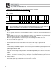
2.6.3 PIO Interface
A PIO interface list is given below.
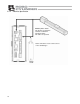
The PIO cable is a flat cable with no connector attached on the end connected to the external equipment.
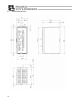
PIO connector (26 pins)
Pin No. Category Signal name
Cable color
1 Brown-1
2
Not used Do not connect anything to this terminal.
Red-1
3 Start
Input for movement start signal
Orange-1
4 Command position 1 Yellow-1
5 Command position 2 Green-1
6 Command position 4 Blue-1
7 Command position 8
Input the position number you want to select.
[1]
Purple-1
8 Gray-1
9
Not used Do not connect anything to this terminal.
White-1
10 [2] * Pause
The moving actuator is paused.
Black-1
11 [3] Reset
Alarms are set.
Brown-2
12 [4] Servo ON
The servo is turned on.
Red-2
13
Input
Not used
Orange-2
14
Do not connect anything to this terminal.
Yellow-2
15
Not used
Do not connect anything to this terminal.
Green-2
16 Completed position 1 Blue-2
17 Completed position 2 Purple-2
18 Completed position 4 Gray-2
19 Completed position 8
The position number to which the positioning
has completed is output. [5]
White-2
20 [6] Position complete
This signal is output upon completion of
movement.
Black-1
21 [7] Home return completion
This signal is output upon completion of home
return.
Brown-3
22 Zone
This signal is output within the range set by
parameters.
Red-3
23 [8] * Alarm
This signal is output when a controller error is
detected.
Orange-3
24 [9] *Emergency stop
This signal is output when an emergency stop
is actuated.
Yellow-3
25
Output
[10] Moving
This signal is output while the motor is running.
Green-3
26
Not used Do not connect anything to this terminal.
Blue-3
Model number of controller-end connector: Hirose HIF6-26 PA-1.27DS
Note: Note: The ports denoted by * operate on the negative (contact-b) logic. Never connect the signal
of any of these ports to an unused port.