ROBO Cylinder ROBO Gripper RCS2 Actuator Operation Manual Third Edition � Two-finger Type , GR8 � IAI America, Inc.
Please Read Before Use Thank you for purchasing our product. This Operation Manual describes all necessary information items to operate this product safely such as the operation procedure, structure and maintenance procedure. Before the operation, read this manual carefully and fully understand it to operate this product safely. The enclosed CD/DVD in this product package includes the Operation Manual for this product.
Table of Contents Safety Guide············································································································ 1 Caution in Handling ································································································· 8 International Standards Compliances······································································ 9 Names of the Parts ································································································ 10 1.
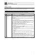
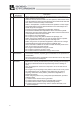
Safety Guide “Safety Guide” has been written to use the machine safely and so prevent personal injury or property damage beforehand. Make sure to read it before the operation of this product. Safety Precautions for Our Products The common safety precautions for the use of any of our robots in each operation. No.
No. 2 2 Operation Description Transportation 3 Storage and Preservation 4 Installation and Start Description � When carrying a heavy object, do the work with two or more persons or utilize equipment such as crane. � When the work is carried out with 2 or more persons, make it clear who is to be the leader and who to be the follower(s) and communicate well with each other to ensure the safety of the workers.
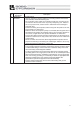
No. 4 Operation Description Installation and Start Description (2) Cable Wiring � Use our company’s genuine cables for connecting between the actuator and controller, and for the teaching tool. � Do not scratch on the cable. Do not bend it forcibly. Do not pull it. Do not coil it around. Do not insert it. Do not put any heavy thing on it. Failure to do so may cause a fire, electric shock or malfunction due to leakage or continuity error.
No. 4 5 4 Operation Description Installation and Start Teaching Description (4) Safety Measures � When the work is carried out with 2 or more persons, make it clear who is to be the leader and who to be the follower(s) and communicate well with each other to ensure the safety of the workers. � When the product is under operation or in the ready mode, take the safety measures (such as the installation of safety and protection fence) so that nobody can enter the area within the robot’s movable range.
No. 6 7 Operation Description Trial Operation Automatic Operation Description � When the work is carried out with 2 or more persons, make it clear who is to be the leader and who to be the follower(s) and communicate well with each other to ensure the safety of the workers. � After the teaching or programming operation, perform the check operation one step by one step and then shift to the automatic operation.
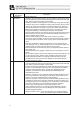
No. 8 9 6 Operation Description Maintenance and Inspection 10 Modification and Dismantle Disposal 11 Other Description � When the work is carried out with 2 or more persons, make it clear who is to be the leader and who to be the follower(s) and communicate well with each other to ensure the safety of the workers. � Perform the work out of the safety protection fence, if possible.
Alert Indication The safety precautions are divided into “Danger”, “Warning”, “Caution” and “Notice” according to the warning level, as follows, and described in the Operation Manual for each model. Level Degree of Danger and Damage Danger This indicates an imminently hazardous situation which, if the product is not handled correctly, will result in death or serious injury.
Caution in Handling 1. Ensure use of the product in the specified conditions, environments and ranges. An operation out of the guarantee may cause a drop in performance or malfunction of the product. 2. Make sure to attach the actuator properly by following this instruction manual. Using the product with the actuator not being certainly retained or affixed may cause abnormal noise, vibration, malfunction or shorten the product life.
International Standards Compliances This actuator complies with the following overseas standards. Refer to Overseas Standard Compliance Manual (ME0287) for more detailed information.
Names of the Parts 1.
1. Specifications Check 1.1 Checking the Product 1. Specifications Check The standard configuration of this product is comprised of the following parts. See the component list for the details of the enclosed components. If you find any fault or missing parts, contact your local IAI distributor. 1.1.1 Parts No. 1 Name Actuator Model Number Refer to “How to Read the Model Nameplate” and “How to Read the Model Number.
(2) XSEL-P/Q Controller 1. Specifications Check No. 1 2 3 4 5 6 7 8 Name Operation Manual for XSEL-P/Q Controller Operation Manual for XSEL-P/Q/PX/QX RC Gateway Function� Operation Manual for PC Software IA-101-X-MW/IA-101-X-USBMW Operation Manual for Teaching Pendant SEL-T/TD/TG Operation Manual for Teaching Pendant IA-T-X/XD Operation Manual for DeviceNet Operation Manual for CC-Link Operation Manual for PROFIBUS Control No.
(5) SCON Controller Name Operation Manual for SCON Controller Operation Manual for SCON-CA Controller� Operation Manual for PC Software RCM-101-MW/RCM-101-USB Operation Manual for Teaching Pendant CON-T/TG Operation Manual for Touch Panel Teaching CON-PT/PD/PG Operation Manual for Simplified Teaching Pendant RCM-E Operation Manual for Data setter RCM-P Operation Manual for Touch Panel Display RCM-PM-01 Operation Manual for DeviceNet Operation Manual for CC-Link Operation Manual for PROFIBUS Control No.
1.1.3 How to Read the Model Nameplate 1. Specifications Check Model Serial number 1.1.4 MODEL RCS2-GR8-I-60-5-20-T1-S-** SERIAL No.
1.2 Specifications � 1.2.1 Specifications Table Rated Output Max. Back and Forth Operation Times Holding Force at Operation Stop (Note 1) Rated Holding Force (Note 2) during Operation Maximum Speed Maximum Acceleration / Deceleration Speed Positioning Accuracy Repeatability (Note 3) (Note 5) (Note 4) (Note 5) Lost Motion Driving System Base Weight Note 1 Note 2 Note 3 Note 4 Note 5 [W] 80 (40 mm per side) 60 [cpm] 60 [N(kgf)] 22.5(2.3) [n(kgf)] 31.3(3.2) [mm/s] 400 [G] 0.3 [mm] � 0.
1.2.2 Allowable Load Moment of the Actuator � 1. Specifications Check Allowable Static Load Moment [N�m] Ma Mb Mc 5.1 5.1 10.4 � � � � Mb � � � � � � � Ma Mc Caution : Set the allowable load moment within the allowable range. Operation above the allowable range may cause malfunction or shortening of the product life.
1.3 Motor • Encoder Cables Motor Cable / Motor Robot Cable (16) (20) (φ 9) L 1 (18) (41) 4 (10) (Front View) 1 4 Controller Side Width AWG18 (Front View) Mechanical Side Electric Signal wire color name Green Red White Black PE U V W Pin No. Pin No. Signal name 1 2 3 4 1 2 3 4 U V W PE Electric wire color Width Red White AWG18 Black (Solderless) Green 17 1. Specifications Check CB-RCC-MA������CB-RCC-MA���-RB (21) 1.3.
1.3.2 Encoder Cable / Encoder Robot Cable CB-RCS2-PA������CB-RCS2-PA���-RB (For SCON, SSEL, XSEL-P/Q) L 1. Specifications Check (41) (14) (15) 1 26 13 (Front View) Width (φ 10) 14 1 10 (25) (37) (13) 9 18 Mechanical Side (Front View) Controller Side Electric wire color Signal name Pin No.
CB-RCBC-PA������CB-RCBC-PA���-RB (For XSEL-J/K) (14) L (36) (57) (15) (33) (25) (φ 8) 1,10 9,18 (Front View) Controller Side Width Electric wire color Signal name Pink Purple White Blue/Red B/V Z/W Orange/White Green/White Pin No. Pin No.
2. Installation 2.1 Transportation 2. Installation [1] Handling of the Robot Unless otherwise specified, the actuators are wrapped individually when the product is shipped out. (1) Handling of the Packed Unit � Do not damage or drop. The package is not applied with any special treatment that enables it to resist an impact caused by a drop or crash. � An operator should never attempt to carry a heavy package on their own. Also, use an appropriate way for transportation.
[2] Handling in Assembled Condition It is applied to the case that this product is assembled with other actuators and shipped out from our factory. (2) Handling after Unpackaged � Appropriately fix the tip of the actuators if it is overhanging so it would not widely shake with external vibration. If the actuator assembly is transported without the ends being secured, do not apply an impact of 0.3G or more.
2.2 Installation and Storage • Preservation Environment [1] Installation Environment 2. Installation The actuator should be installed in a location other than those specified below. Also provide sufficient work space required for maintenance inspection.
2.3 How to Installation This chapter explains how to install the actuator on your mechanical system. 2.3.1 Installation Orientation � : Available � : Not available Horizontal Installation Vertical Installation � Installation orientation Horizontal Installation 2. Installation Shown below are the basic concepts for the product attachment. Pay special attention when deciding how to install the product (Except with custom-order models).
2.3.2 [1] Installation Installation of the Main Unit 2. Installation There are T-shaped grooves for M6 on the right and left of the base. Utilize these T-slots for the attachment of bracket and other equipments by putting in nuts and tightening with screws. Detail A [2] Nut M6 T-nut (recommended) or square nut Screw M6�8 (Note 1) Note1 Thread length should be 8mm maximum due to the T-slot depth.
[3] Installation of the Finger Attachments Please prepare the finger attachments separately. � Finger Mounting Plate Screw Attachment Positions 2. Installation M4, effective depth 7 Finger Profile M4, through Caution : Pay attention to the selection of the screw length. Use of inappropriate length of screws may cause a destruction of the tapped holes, insufficient holding strength of the actuator or interference on the driving part, which may result in a drop of the accuracy or an unexpected accident.
3. Connecting to the Controller 3. Connecting to the Controller As the connection cable for the controller and actuator, use the IAI-dedicated controller and dedicated connection cable. In this section, describes how to lay out the wirings for the single axis use.
[Connection to the X-SEL controller] Dedicated Cable (Connect RCS2 with the dedicated controller) 3. Connecting to the Controller Dedicated Controller XSEL Robot cable r=58mm or more (Movable Use) Standard cable r=93mm or more (Fixed Use) Apply a robot cable for moveable area.
Warning: For wiring, please follow the warnings stated below. When constructing a system as the machinery equipment, pay attention to the wiring and connection of each cable so they are conducted properly. Not following them may cause not only a malfunction such as cable breakage or connection failure, or an operation error, but also electric shock or electric leakage, or may even cause a fire. • Use dedicated cables of IAI indicated in this instruction manual.
• Do not let the cable bend, kink or twist. 3. Connecting to the Controller • Do not pull the cable with a strong force. • Pay attention not to concentrate the twisting force to one point on a cable. • Do not pinch, drop a heavy object onto or cut the cable. • When a cable is fastened to affix, make sure to have an appropriate force and do not tighten too much. Do not use spiral tube in any position where cables are bent frequently.
• PIO line, communication line, power and driving lines are to be put separately from each other and do not tie them together. Arrange so that such lines are independently routed in the duct. 3. Connecting to the Controller Power Line Duct I/O Line (Flat Cable, etc.) • If using a cable track, arrange the wiring so that there is no entanglement or kink of the cables in the cable carrier or flexible tube, and do not bind the cables so that the cables are relatively free.
4� Caution for Operation (Finger Operations) [1] Finger Stroke The design stroke of the two- finger type is a sum of travel distances of both fingers. In other words, the travel distance of one fingers is one-half the design stroke. [2] Home-Return Direction The side of that the fingers are open (closer to the side cover) is defined as the home position. [3] Position Specification caution [4] Speed/acceleration Commands Speed/acceleration commands are specified based on a value per finger.
5� Maintenance Inspection 5.1 Inspection Items and Inspection Schedule 5. Maintenance Inspection Have maintenance inspections following the intervals below. The calculation is conducted under the condition that there are 8 working hours per day. Have inspections more frequently if the operation frequency is high for night and day continuous operation, etc.
5.4 Grease Supply 5.4.1 Applied Grease on Guides The following grease is applied when the product is shipped out from IAI factory. Linear guide Kyodo Yushi Mul Temp SRL Apart from above, there are equivalent sorts of grease sold in the market. For details contact a grease supplier, provide the grease name shown above and ask them to select an equivalent. Listed below are some equivalents for an example. Supply grease only on the linear guide part. 5.
6. External Dimensions T-slot for unit mounting Cable joint connectors *1 6. External Dimensions Detail: T-slot for unit mounting 34 Stroke 20 40 (60) (80) 100 (120) (200) A 22 42 62 82 102 122 202 B 10 20 30 40 50 60 100 C 106.4 126.4 146.4 166.4 186.4 206.4 286.4 D 104 124 144 164 184 204 284 E 100 120 140 160 180 200 280 Weight (kg) 1.8 1.9 1.9 2.0 2.0 2.1 2.
7. Warranty 7.1 Warranty Period One of the following periods, whichever is shorter: � 18 months after shipment from our company � 12 months after delivery to the specified location � 2,500 hours of operation 7.
7.5 Conditions of Conformance with Applicable Standards/Regulations, Etc., and Applications (1) If our product is combined with another product or any system, device, etc., used by the customer, the customer must first check the applicable standards, regulations and/or rules. The customer is also responsible for confirming that such combination with our product conforms to the applicable standards, etc.
Change History Revision Date Description of Revision 2010.10 First Edition 2012.09 Second Edition Please Read Before Used added International Standards Compliances added Additions and Changes made in Safety Guide contents Contents changed in 3. Warranty in Pg.15 to Pg 16. 2012.
� �
Manual No.: ME3659-3A (November 2012) � � � � � � � � � � � � � � � � � � � � � � � � � � � � � � � � � � � � � � � � � � � � � � � � � � � � � � � � � � � � � � � � � � Head Office: 577-1 Obane Shimizu-KU Shizuoka City Shizuoka 424-0103, Japan TEL +81-54-364-5105 FAX +81-54-364-2589 website: www.iai-robot.co.jp/ Technical Support available in USA, Europe and China Head Office: 2690 W.