ROBO Cylinder RCS2 Actuator Rotary Hollow Rotary Operating Manual Fourth Edition Rotary, RT6, RT6R, RT7R Hollow Rotary, RTC8L, RTC8HL, RT10L, RTC12L IAI America, Inc.
Please Read Before Use Thank you for purchasing our product. This Operation Manual describes all necessary info rmation to operate this product safely such as the operation procedure, structure and maintenance procedure. Before operation, read this manual carefully and fully understand it to operate this product safely. The enclosed CD or DVD in this product package includes the Operation Manual for this product.
Table of Contents Safety Guide.................................................................................................................... 1 Handling Precautions ...................................................................................................... 8 International Standards Compliances ............................................................................ 10 Names of the Parts ......................................................................................................
7. How to Select a Hollow Rotary Actuator Model ....................................................... 35 8. Options.................................................................................................................... 37 8.1 8.2 8.3 Limit Switch ................................................................................................................................ 37 Brake ...............................................................................................................
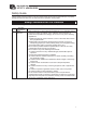
Safety Guide “Safety Guide” has been written to use the machine safely and so prevent personal injury or property damage beforehand. Make sure to read it before the operation of this product. Safety Precautions for Our Products The common safety precautions for the use of any of our robots in each operation. No.
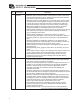
No. 2 2 Operation Description Transportation 3 Storage and Preservation 4 Installation and Start Description When carrying a heavy object, do the work with two or more persons or utilize equipment such as crane. When the work is carried out with 2 or more persons, make it clear who is to be the leader and who to be the follower(s) and communicate well with each other to ensure the safety of the workers.
No. 4 Operation Description Installation and Start Description (2) Cable Wiring Use our company’s genuine cables for connecting between the actuator and controller, and for the teaching tool. Do not scratch on the cable. Do not bend it forcibly. Do not pull it. Do not coil it around. Do not insert it. Do not put any heavy thing on it. Failure to do so may cause a fire, electric shock or malfunction due to leakage or continuity error.
No. 4 5 4 Operation Description Installation and Start Teaching Description (4) Safety Measures When the work is carried out with 2 or more persons, make it clear who is to be the leader and who to be the follower(s) and communicate well with each other to ensure the safety of the workers. When the product is under operation or in the ready mode, take the safety measures (such as the installation of safety and protection fence) so that nobody can enter the area within the robot’s movable range.
No. 6 7 Operation Description Trial Operation Automatic Operation Description When the work is carried out with 2 or more persons, make it clear who is to be the leader and who to be the follower(s) and communicate well with each other to ensure the safety of the workers. After the teaching or programming operation, perform the check operation one step by one step and then shift to the automatic operation.
No. 8 9 6 Operation Description Maintenance and Inspection 10 Modification and Dismantle Disposal 11 Other Description When the work is carried out with 2 or more persons, make it clear who is to be the leader and who to be the follower(s) and communicate well with each other to ensure the safety of the workers. Perform the work out of the safety protection fence, if possible.
Alert Indication The safety precautions are divided into “Danger”, “Warning”, “Caution” and “Notice” according to the warning level, as follows, and described in the Operation Manual for each model. Level Degree of Danger and Damage Danger This indicates an imminently hazardous situation which, if the product is not handled correctly, will result in death or serious injury.
Handling Precautions 1. Do not set speeds and accelerations/decelerations exceeding the respective ratings. Do not set speeds and accelerations/decelerations exceeding the respective ratings. It may lead to vibration, failure, or shorter life. 2. Keep the inertial moment, load moment and thrust load within their respective allowable values. Keep the inertial moment, load moment and thrust load within their respective allowable values.
6. Whenever possible, use the RTC8L and RTC8HL types at speeds of 100 deg/s or more. If these actuators are operated at low speeds below 100 deg/s, the actuators will move slightly as they move. Even when the operating speed is low, however, vibration will decrease as the speed increases in the lowspeed range. Check the actual vibration level at the speeds you intend to use. Take note that the larger the tool, the greater the vibration becomes at ends. 7. Transportation 7.
International Standards Compliances This actuator complies with the following overseas standard. Refer to Overseas Standard Compliance Manual (ME0287) for more detailed information.
Names of the Parts The name of each part of the actuator is shown as follows. 1. Rotary 1.1 RT6 Drive shaft Motor cover Frame Motor bracket 1.
1.
2.
1. Checking the Product 1. Checking the Product This product, if of a standard configuration, consists of the items specified below. Caution: Check the items included in the package by referring to the packing slip. Should you find any item missing or bearing a wrong model number, please contact IAI or your IAI dealer. 1.1 Components No. 1 Item Actuator Model number Remarks Refer to “How to Read the Nameplate” and “How to Read the Model Number.
(2) XSEL-P/Q controllers No. Name Control number Operation Manual for XSEL-P/Q Controller ME0148 2 Operation Manual for XSEL-P/Q/PX/QX - RC Gateway Function ME0188 3 Operation Manual for PC Software IA-101-X-MW/IA-101-X-USBMW ME0154 4 Operation Manual for Teaching Pendant SEL-T/TD/TG ME0183 5 Operation Manual for Teaching Pendant IA-T-X/XD ME0160 6 Operation Manual for DeviceNet ME0124 7 Operation Manual for CC-Link ME0123 8 Operation Manual for PROFIBUS ME0153 1.
1. Checking the Product 1.3 How to Read the Nameplate Model number Serial number 1.
2. 2.1 Specifications Rotary RT6 1/18 RT7R 1/4 Oscillation angle 300 deg Maximum speed 500 deg/s Rated acceleration 0.3 G Rated Torque 2.4 N•m Allowable inertial moment Driving System -2 0.764 N•m 2 2.5 × 10 kg•m Max. Ball Speed Reducer Ball Speed Reducer + Timing Belt Positioning Accuracy Repeatability 1.25 × 10⁻³ kg•m2 Max. Timing Belt r0.02 mm Backlash 0.1 deg Max. 0.1 deg Max. Allowable load moment/ 6.8 N•m Max. 8.9 N•m Max. Thruster Load 100 N Max.
2.2 Hollow Rotary 2. Specifications RTC8L RTC8HL Deceleration ratio 1/24 Oscillation angle 0 to 359.99 deg Maximum speed 750 deg/s Acceleration Output torque Allowable inertial moment Driving System Positioning Accuracy Repeatability Backlash Allowable load moment/ Thruster Load Encoder pulse count*1 *1 1/15 1/24 0 to 359.99 deg 1200 deg/s 0.1 G to 0.3 G 0.55 N•m 750 deg/s 0.1 G to 0.3 G 0.53 N•m 2 0.85 N•m 2 0.011 kg•m Max. 0.010 kg•m Max. 0.017 kg•m2 Max.
3. 3.1 Installation Environment, Storage/Preservation Environment Installation Environment 3.2 Storage Environment/Preservation The storage/preservation environment conforms to the installation environment. If the robot is to be stored/preserved for a prolonged period of time, be sure the robot will not be exposed to condensation. Unless otherwise specified, desiccant is not placed in the carton when shipped.
4. Installation 4.1 Rotary Type 4.1.1 Installing the Actuator 4. Installation Utilize the tapped holes either on the front or on the bottom for installation. Positions of the tapped holes are as shown in the following figures. x RT6 4-M6 Depth 12 Caution: Never use long screws exceeding the maximum screw-in depth. Use of such long screws may cause damage to the internal mechanisms and electrical parts.
x RT6R 4. Installation 4-M6 Depth 12 x RT7R 9 through hole 4-M6 Depth 12 2-M8 Depth 12 Caution: Never use long screws exceeding the maximum screw-in depth. Use of such long screws may cause damage to the internal mechanisms and electrical parts.
4.2 Hollow Rotary 4.2.1 Installing the Actuator and a Tool on the Output Shaft x The maximum screw-in depth varies depending on the mounting surface. Determine an appropriate screw length by referring to the figure provided below. 4. Installation Caution: Never use long screws exceeding the maximum screw-in depth. Use of such long screws may cause damage to the internal mechanisms and electrical parts. x Each mounting surface has circular holes and slotted holes for positioning pins.
[RTC10L] 2-4 H7 +0.010 0 Depth 5 8-M4 Depth 6 4. Installation 4 +0.05 Depth 4 0 4-M5 Depth 10 40 (Through) 2-4 +0.05 Depth 4 (Same on the opposite side) 0 8-M5 Depth 10 (Same on the opposite side) +0.05 2-4 0 Depth 4 (Same on the opposite side) 4 +0.05 0 Depth 4 [RTC12L] 8-M5 Depth 8 2-5 H7 +0.012 0 Depth 6 5 +0.05 Depth 4 0 54 (Through) 2-5 +0.05 0 4-M6 Depth 12 Depth 4 (Same on the opposite side) 8-M6 Depth 12 (Same on the opposite side) 2-5 +0.
Tightening torque When mounting the tool or frame on the output shaft, do so according to the tightening torques listed below. 4. Installation Recommended tightening torque N•cm (kgf•cm) Tapped hole diameter Bearing surface - Copper Bearing surface - Aluminum M4 359 (36.7) 176 (18) M5 727 (74.2) 342 (34.9) M6 1234 (126) 536 (54.7) * Hexagonal socket head bolt of strength category 10.9 Tightening screws x Use high-tension bolts of ISO-10.9 or higher.
4.2.2 Installation Direction and Mounting Surface Install the actuator using the mounting surface corresponding to the load direction. (1) Installing horizontally Load direction 4.
4.2.3 Load Offset Distance 4. Installation Vibration tends to increases as the center of gravity of the work part becomes farther away from the center of the rotational axis. Design an appropriate tool by using the table as a guide. 26 Model Offset distance [m] RTC8L 0.10 RTC8HL 0.12 RTC10L 0.15 RTC12L 0.
5. Connecting to the Controller The following explains the wiring method by assuming use of a single axis. 5.1 Wiring The actuator and controller are connected by the motor cable and encoder cable (genuine part) via connectors. Motor cable Controller 5. Connecting to the Controller Actuator Encoder cable Example of Connection with XSEL Controller [For details on the relay cables, refer to 9, “Motor/Encoder Cables.
When designing an application system using actuators and controllers, incorrect wiring or connection of each cable may cause unexpected problems such as a disconnected cable or poor contact. This section explains prohibited handling of cables. Read the information carefully to connect the cables properly. x Do not let the cable flex at a single point. Steel band (piano wire) 5. Connecting to the Controller Bundle loosely. x Do not let the cable bend, kink or twist.
z Cautions for use of a cable track z The actuator cable is not a robot cable, so never store the actuator cable in a cable track. z The bending radius of the cable track must not exceed the minimum bending radius of the cables. [Refer to 9, “Motor/Encoder Cables.”] z Do not let the cable get tangled or kinked in a cable track or flexible tube. When bundling the cable, keep a certain degree of flexibility (so that the cable will not become too taut when bent).
6. Notes on Operation 6.1 Rotary 6.1.1 Backlash and Positioning Accuracy Repeatability 6. Notes on Operation The rotary actuator has backlash (play). If the movement is smaller than the backlash, there may be a possibility that the drive shaft does not rotate.
(2) Home return When performing a home-return operation to the rotary, the rotary direction to home-return differs as shown in the figures below due to the position where the shaft is when the home-return operation starts. 1) If the shaft does not detect the sensor at the home-return start, it moves counterclockwise in the view of the shaft tip ([1]), and it reverses if sensor is detected ([2]), and then stops when the Zphase is detected. (Refer to Figure 1.
6.1.3 Conditions for Loads Installable to Shaft of Rotary There is a limitation for the objects that are available to attach on the shaft of the rotary determined by its limit ranges of the allowable load moment, rated torque and allowable moment of inertia. Please note that a use of the product in a condition beyond the limit range may shorten the product’s life or cause malfunction. The table below shows the allowable load moment, rated torque and allowable moment of inertia for each model.
6.2 Hollow Rotary 6.2.1 Operation Range and Home Return (1) Range of Operation z Rotational axis/Normal mode In the absolute position specification mode, the actuator operates in the range shown below. The maximum range of rotation varies depending on the deceleration ratio. Maximum range of rotation 15 0 to 9999.99 18 0 to 9999.99 24 0 to 7670.99 30 0 to 6140.99 z Rotational axis/Index mode In the absolute position specification mode, the actuator operates in the range of 0 to 359.99 degrees.
6.2.2 Brake 6. Notes on Operation x The actuator’s brake is designed to hold the work part in place. Do not use it to decelerate the actuator or actuate an emergency stop. x To release the brake manually, use the brake switch on the controller. (Note) If the actuator must hold the work part in place, check the holding torque.
7. How to Select a Hollow Rotary Actuator Model Select an appropriate model based on the shape and mass of the work part on the output shaft, by referring to the figure and graphs shown below. (1) Disk-shaped work part at the center of the output shaft J = M•r2/2 (Radius of disk) Disk-shaped work part on RTC10L Mass of disk [kg] Mass of disk [kg] 7.
(2) Work part offset from the center of the output shaft J = M•r2 7. How to Select a Hollow Rotary Actuator Model (Offset distance) Offset work part Mass of work part [kg] Mass of work part [kg] Offset work part Offset distance [cm] Offset distance [cm] Offset work part Mass of work part [kg] * When the rotational axis is used horizontally, a load torque will generate due to the gravitational acceleration if the work part is installed at a position offset from the center of rotation.
8. 8.1 Options Limit Switch Normally during the home return operation, the slider contacts the stopper and reverses, and then detect Z-phase (“push method”). The home limit switch (L) is used to cause the actuator to reverse not upon contact, but using a proximity sensor. The limit switch is a standard feature on both the rotary type and hollow rotary type. 8.
9. Motor/Encoder Cables All cables apply commonly regardless of the actuator model name. The applicable cables vary depending on the connected controller. Correspondence table of controllers and motor/encoder cables XSEL-J/K XSEL-P/Q, SSEL, SCON Applicable cables [1] Motor cable [1], [2], [3] [1], [4] CB-X-MA*** * *** indicates the cable length (L). Up to 30 m can be specified.
[3] Limit switch cable CB-X-LC*** * *** indicates the cable length (L). Up to 30 m can be specified. Example) 080 = 8 m [Minimum bending radius] Moving cable: 33 mm (Front view) (Front view) Mounted cable: 22 mm Actuator end Controller end Wire Color Signal Signal Color Light blue Light blue Pink Pink Light green Light green Orange Orange Gray Gray 1B/ Light blue 1B/ Light blue Wire Note) “1B” indicates one black dot.
10. Maintenance/Inspection Daily and periodic inspections are essential to making sure your actuator will operate safely and efficiently. Before carrying out each inspection, check the applicable maintenance/inspection items listed below. 10.1 Inspection Items and Schedule Conduct visual inspection and add grease at the applicable schedules specified below. The following schedule is based on eight hours of operation daily.
10.2 Visual Inspection of the Exterior In the visual inspection of the exterior, check the following items. Actuator Loosening of actuator mounting bolts, etc. Cables Scratches, proper connection of connectors Overall Noise, vibration x With the hollow rotary type, grease that has been applied to the gears may drip depending on the environment. Clean the areas dirtied by grease or add grease, as necessary. 10.3 Exterior Cleaning x Clean the exterior of the actuator as necessary.
(2) How to add grease [1] Remove the screws mounting the rear cover (countersunk machine screw M2.6 x 6). Pull the rear cover slightly from the actuator frame. (Do not forcibly pull the cables inside.) Round terminal 10. Maintenance/Inspection [2] While turning the gears, apply grease from the rear opening just enough to coat the bottom of the teeth. (As the input shaft is turned, the output gears turn.) Thereafter, turn the grease several times in both directions to let the grease spread evenly. Turn.
[3] Install and mount the front cover and rear cover. Be careful not to pinch the cables when mounting the rear cover. 43 10. Maintenance/Inspection Warning: x Never use fluorine grease. If fluorine grease is mixed with lithium grease, grease function will drop and the mechanical parts will be damaged. x Do not add grease any more than necessary. Excess grease may flow to the electronic components and cause malfunction.
11. External Dimensions 11.1 Rotary x RT6 11. External Dimensions 4-M6 Depth 12 Secure 40 Min. 44 Cable Joint Connectors *1 * For the connection to motor cable, encoder cable and limit switch cable Weight [kg] 1.
x RT6R 4-M6 Depth 12 11. External Dimensions Cable Joint Connectors *1 Secure 40 Min. * For the connection to motor cable, encoder cable and limit switch cable Weight [kg] 2.
x RT7R 9 through hole 4-M6 Depth 12 Cable Joint Connectors *1 11. External Dimensions 2-M8 Depth 12 Secure 40 Min. * For the connection to motor cable, encoder cable and limit switch cable Weight [kg] 46 2.
Hollow Rotary 11.2 x RTC8L, RTC8HL Depth 3.5 4 +0.05 Depth 3.5 0 4-M5 Depth 10 +0.05 0 Depth 3.5 6-M4 Depth 6 4 * * * * * * 2 - 4 H7 +0.010 0 30 (Through) 11. External Dimensions Depth 5 4-M5 Depth 10 4 +0.05 Depth 3.5 0 * * 4-M5 Depth 10 (Maximum screw-in depth: 9) 4 +0.05 0 2.3 RTC8HL 2.4 Depth 4 4 +0.05 Depth 4 0 (Note) The dimension denoted by “*” is different between the RTC8L and RTC8HL .
8-M4 Depth 6 2-4 +0.05 0 2-4 H7 40 (Through) +0.010 0 Depth 5 8-M5 Depth 10 (Same on the opposite side) 4 +0.05 Depth 4 0 4-M5 Depth 10 +0.05 4 0 Depth 4 48 2-4 +0.05 Depth 4 (Same on the opposite side) 0 Depth 4 (Same on the opposite side) 11. External Dimensions x RTC10L 3.
x RTC12L 8-M5 Depth 8 +0.05 0 54 (Through) 2-5 2-5 2-5 H7 +0.012 0 Depth 6 11. External Dimensions Depth 4 (Same on the opposite side) 8-M6 Depth 12 (Same on the opposite side) +0.05 0 Depth 4 (Same on the opposite side) +0.05 0 5 +0.05 Depth 4 0 5 4-M6 Depth 12 Depth 4 6.
12. Warranty 12.1 Warranty Period One of the following periods, whichever is shorter: x 18 months after shipment from IAI x 12 months after delivery to the specified location x 2,500 hours of operation 12.2 Scope of Warranty Our products are covered by warranty when all of the following conditions are met. Faulty products covered by warranty will be replaced or repaired free of charge: (1) The breakdown or problem in question pertains to our product as delivered by us or our authorized dealer.
12.5 Conditions of Conformance with Applicable Standards/Regulations, Etc., and Applications (1) If our product is combined with another product or any system, device, etc., used by the customer, the customer must first check the applicable standards, regulations and/or rules. The customer is also responsible for confirming that such combination with our product conforms to the applicable standards, etc.
Change History Revision Date August 2010 June 2011 Description of Revision Second Edition P. 8 Third Edition P. 12 Added “Hollow Rotary Actuator” in “Name of Each Part.” P. 13 to 15 Added 1, “Checking the Product” P. 17 Added “Hollow Rotary Actuator” in 2, “Specification.” P. 21 to 22 Added “Hollow Rotary Actuator” in 5, “Installation.” P. 32 to 33 Added “Hollow Rotary Actuator” in 7, “Notes on Operation.” P. 34 to 35 Added 8, “How to Select a Hollow Rotary Actuator Model.” P.
Catalog No.: ME3658-4A Head Office: 2690 W. 237th Street, Torrance, CA 90505 TEL (310) 891-6015 FAX (310) 891-0815 Chicago Office: 1261 Hamilton Parkway, Itasca, IL 60143 TEL (630) 467-9900 FAX (630) 467-9912 Atlanta Office: 1220 Kennestone Circle, Suite 108, Marietta, GA 30066 TEL (678) 354-9470 FAX (678) 354-9471 website: www.intelligentactuator.com Ober der Röth 4, D-65824 Schwalbach am Taunus, Germany TEL 06196-88950 FAX 06196-889524 IAI (Shanghai) Co., Ltd.