Thin and Small ROBO Cylinder RCS2 Actuator Table Type Operating Manual Second Edition Short Types Compact Type TCA5N Short Types Wide Type TWA5N Short Types Flat Type TFA5N IAI America, Inc.
Please Read Before Use Thank you for purchasing our product. This Operation Manual describes all necessary information to operate this product safely such as the operation procedure, structure and maintenance procedure. Before operation, read this manual carefully and fully understand it to operate this product safely. The enclosed CD or DVD in this product package includes the Operation Manual for this product.
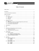
Table of Contents Safety Guide..................................................................................................................................1 Precautions ...................................................................................................................................8 International Standards Compliances ...........................................................................................9 Names of the Parts..........................................................
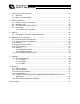
7. Connecting with the Controller .............................................................................................29 7.1 Wiring 29 7.2 Motor • Encoder Cables ..............................................................................................32 8. Notes on Operation ..............................................................................................................34 8.1 Placing a Load on the Actuator .......................................................................
Safety Guide “Safety Guide” has been written to use the machine safely and so prevent personal injury or property damage beforehand. Make sure to read it before the operation of this product. Safety Precautions for Our Products The common safety precautions for the use of any of our robots in each operation. No.
No. 2 2 Operation Description Transportation 3 Storage and Preservation 4 Installation and Start Description Ɣ When carrying a heavy object, do the work with two or more persons or utilize equipment such as crane. Ɣ When the work is carried out with 2 or more persons, make it clear who is to be the leader and who to be the follower(s) and communicate well with each other to ensure the safety of the workers.
No. 4 Operation Description Installation and Start Description (2) Cable Wiring Ɣ Use our company’s genuine cables for connecting between the actuator and controller, and for the teaching tool. Ɣ Do not scratch on the cable. Do not bend it forcibly. Do not pull it. Do not coil it around. Do not insert it. Do not put any heavy thing on it. Failure to do so may cause a fire, electric shock or malfunction due to leakage or continuity error.
No. 4 5 4 Operation Description Installation and Start Teaching Description (4) Safety Measures Ɣ When the work is carried out with 2 or more persons, make it clear who is to be the leader and who to be the follower(s) and communicate well with each other to ensure the safety of the workers. Ɣ When the product is under operation or in the ready mode, take the safety measures (such as the installation of safety and protection fence) so that nobody can enter the area within the robot’s movable range.
No. 6 7 Operation Description Trial Operation Automatic Operation Description Ɣ When the work is carried out with 2 or more persons, make it clear who is to be the leader and who to be the follower(s) and communicate well with each other to ensure the safety of the workers. Ɣ After the teaching or programming operation, perform the check operation one step by one step and then shift to the automatic operation.
No. 8 9 10 11 6 Operation Description Maintenance and Inspection Description Ɣ When the work is carried out with 2 or more persons, make it clear who is to be the leader and who to be the follower(s) and communicate well with each other to ensure the safety of the workers. Ɣ Perform the work out of the safety protection fence, if possible.
Alert Indication The safety precautions are divided into “Danger”, “Warning”, “Caution” and “Notice” according to the warning level, as follows, and described in the Operation Manual for each model. Level Degree of Danger and Damage Symbol Danger This indicates an imminently hazardous situation which, if the product is not handled correctly, will result in death or serious injury.
Precautions 1. Do not set speeds and accelerations/decelerations equal to or greater than the respective ratings. If the actuator is operated at a speed or acceleration/deceleration exceeding the allowable value, abnormal noise or vibration, failure, or shorter life may result. In the case of interpolated operation of combined axes, the speed and acceleration/deceleration settings should correspond to the minimum values among all combined axes. 2. Keep the load moment within the allowable value.
International Standards Compliances This actuator complies with the following overseas standard. Refer to Overseas Standard Compliance Manual (ME0287) for more detailed information.
Names of the Parts The names of the actuator parts are indicated below. In this manual, the right and left are determined by viewing the actuator from the top and from the motor side. Also, the front side means the side opposite from the motor. 1. Short Types 1.1 Compact types RCS2-TCA5N Right Side Connector cover Table Front Rear Left Side Cable Front Plate Main Body (Aluminum Frame) * Refer to “External Dimensions” for details. 1.
1.3 Flat types RCS2-TFA5N Right Side Connector cover Table Front Rear Left Side Front Plate Cable Main Body (Aluminum Frame) * Refer to “External Dimensions” for details. Caution: When the table has moved away from its home position, there is a gap between the table and the motor unit. Keep hands clear of gap.
1. Checking the Product 1. Checking the Product If based on a standard configuration, this product consists of the items listed below. Caution: Check the packed items against the packing specification. Should you find a wrong model or any missing item, please contact your IAI dealer or IAI. 1.1 Parts No. 1 Item Actuator Model Number Refer to “How to Read the Model Nameplate” and “How to Read the Model Number.
Control No. ME0157 ME0154 ME0183 ME0160 ME0124 ME0123 ME0153 (3) SCON controller No. Name 1 SCON Controller Operation Manual 2 PC Software RCM-101-MW/RCM-101-USB Operation Manual 3 Teaching Pendant CON-T/TG Operation Manual 4 Touch Panel Teaching CON-PT/PD/PG Operation Manual 5 Simple Teaching Pendant RCM-E Operation Manual 6 Data Setter RCM-P Operation Manual 7 Touch Panel Display RCM-PM-01 Operation Manual 8 DeviceNet Operation Manual 9 CC-Link Operation Manual 10 PROFIBUS Operation Manual Control No.
1. Checking the Product 1.4 How to Read the Model Number R C S 2 - T C A 5 N - I - 6 0 - 2 . 5 - 5 0 - T 2 - P - K 1 - ** Short Type Compact Type TCA5N Wide Type TWA5N Flat Type TFA5N I : Incremental 60 : 60W 2.5/5.0/10.
2. Specifications Type Motor capacity (W) TCA5N TWA5N TFA5N 60 Strokes and maximum speed limits (Unit: mm/s) Horizontal/ Maximum speed Lead (mm) Vertical 50 Horizontal 125 2.5 Vertical 125 Horizontal 250 5.0 Vertical 230 Horizontal 280 10.0 Vertical 230 (2) Maximum acceleration/deceleration and payload capacity Maximum acceleration/deceleration Motor capacity Lead (mm) Type (G) (W) Horizontal 0.2 2.5 Vertical 0.2 TCA5N Horizontal 0.3 TWA5N 60 5.0 Vertical 0.2 TFA5N Horizontal 0.3 10.0 Vertical 0.
3. Life As a rough guide, the table below shows the life of each actuator type when operated at the maximum payload capacity and maximum acceleration/deceleration. 3.
4. 4.1 Installation and Storage/Preservation Environment Installation Environment Install the actuator by avoiding the locations listed below. In general, the actuator should be installed in an environment where the operators can work without wearing protective gears. Also provide enough space to perform maintenance/inspection. If the actuator is used in any of the following locations, provide sufficient shielding measures: x Location where noise generates due to electrostatics, etc.
5. Transportation 5. Transportation 5.1 Handling of Robot 5.1.1 Handling of the Packed Product Unless otherwise specified, the actuator is shipped with each axis packaged separately. x Do not damage or drop. The package is not applied with any special treatment that enables it to resist an impact caused by a drop or crash. x Transport a heavy package with at least more than two operators. Consider an appropriate method for transportation.
5.2 Handling in Assembled Condition x When carrying the actuator, exercise caution not to bump it against nearby objects or structures. x Secure the table to prevent sudden movement during transport. x If any end of the actuator is overhanging, secure it properly to avoid significant movement due to external vibration. x When transporting the assembly without the ends of the actuators fastened, do not subject the assembly to an impact of 0.3 G or more.
6. Installation 6.1 Installation of Main Unit 6.1.1 TCA5N This actuator has tapped holes for mounting so it can be fixed from the rear side. Also, there is a reamed hole and a long hole for positioning pins. (Note) When installing the unit in the horizontally oriented wall mount, put the connector cover of the cable up. (Note) There is Nylok applied to the tapped holes on the unit. Remove the Nylok when installing the unit. 40 Long hole 50 5 +0.03 depth 0 2-M5 depth 10 5 4.
6.1.2 TWA5N This actuator has tapped holes for mounting so it can be fixed from the rear side. Also, there is a reamed hole and a long hole for positioning pins. (Note) When installing the unit in the horizontally oriented wall mount, put the connector cover of the cable up. (Note) There is Nylok applied to the tapped holes on the unit. Remove the Nylok when installing the unit. 40 Long hole 50 5 + 0.03 depth 0 5 4-M5 depth 10 10 Reamed hole φ5 + 0.
6.1.3 TFA5N This actuator has tapped holes for mounting so it can be fixed from the rear side. Also, there is a reamed hole and a long hole for positioning pins. (Note) When installing the unit in the horizontally oriented wall mount, put the connector cover of the cable up. (Note) There is Nylok applied to the tapped holes on the unit. Remove the Nylok when installing the unit. 40 Long hole 50 5 + 0.030 0 depth 5 3-M5 depth 10 37 9 4.5 77 6. Installation 6 15 9 6.5 46.5 33 6.
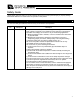
6.2 Installation of the Load 6.2.1 TCA5N x Please attach the load to the device using the tapped holes in the front plate of the table type. x There are also tapped holes and a reamed hole in the top surface of the table. Please use these to attach the load. x There is one reamed hole on the slider in the top surface of the table, so if you need to be able to secure and detach the load multiple times, please use this hole.
φ5 +0.03 depth 5 0 36 6 11 16 5 + 0.03 depth 5 0 48 26 35 69 71 4- M5 depth 12 26 48 φ 5 +0.03 depth 5 0 4-M5 depth 8 6 28 10 6. Installation Front plate 48 76 5 +0.03 depth 0 5 56 Top side of table Caution: x A work part shall be mounted on a machined plane or a plane with equivalent precision, and the flatness shall be 0.01 mm/m or less. If sufficient flatness is not secured, the table is deformed when mounting and fixing a work part, causing malfunction.
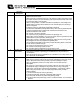
6.2.2 TWA5N x Please attach the load to the device using the tapped holes in the front plate of the table type. x There are also tapped holes and reamed holes in the top surface of the table. Please use these to attach the load. x There is one reamed hole on the slider in the top surface of the table, so if you need to be able to secure and detach the load multiple times, please use this hole.
depth 5 φ5 + 0.03 0 16 30 36 63 65 6 depth 5 5 +0.03 0 42 27 4- M5 depth 12 20 40 80 6. Installation Front plate φ5+ 0.03 0 depth 5 60 10 4-M 5 depth 8 48 5 6 76 + 0.03 0 depth 5 56 Top side of table Caution: x A work part shall be mounted on a machined plane or a plane with equivalent precision, and the flatness shall be 0.01 mm/m or less. If sufficient flatness is not secured, the table is deformed when mounting and fixing a work part, causing malfunction.
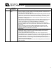
6.2.3 TFA5N x Please attach the load to the device using the tapped holes in the front plate of the table type. x There are also tapped holes and a reamed hole in the top surface of the table. Please use these to attach the load. x There is one reamed hole on the slider in the top surface of the table, so if you need to be able to secure and detach the load multiple times, please use this hole.
depth 5 φ5 + 0.030 0 26 20 16 44 49 2- M5 depth 12 46 36 3 38.5 6 5 +0.030 depth 5 0 24 91 95 16 6. Installation Front plate φ 5 +0.030 depth 5 0 28 57 4-M 5 depth 8 48 5 +0.030 depth 5 0 6 76 56 Top side of table Caution: x A work part shall be mounted on a machined plane or a plane with equivalent precision, and the flatness shall be 0.01 mm/m or less. If sufficient flatness is not secured, the table is deformed when mounting and fixing a work part, causing malfunction.
7. 7.1 Connecting with the Controller Wiring x In an application where the cable cannot be affixed, use the actuator in such a way that the cable will only deflect by its dead weight or give consideration to minimizing the load received by the cable such as using a self-supporting cable hose or wiring the cable at a large radius. x Do not cut and shorten the cable or reconnect the cut end to extend the cable. x The standard cable has excellent flexibility, but it is not a robot cable.
When building an application system using the actuator and controller, incorrect wiring or connection of each cable may cause broken wire, poor contact or other unexpected problem. The prohibited items relating to cable wiring are explained below. x Do not cut and reconnect the cable to extend or shorten the cable. x If the cable cannot be secured, reduce the load on the cable by allowing it to deflect only by the weight of the cable or wire it in a self-standing cable hose, etc., having a large radius.
x When fixing the cable, provide a moderate slack and do not tension it too tight. Do not use a spiral tube where the cable flexes frequently. x Separate the I/O and communication lines from the power and drive lines. Do not wire them together in the same duct. 7. Connecting with the Controller Power line Duct I/O lines (flat cable) x Pay attention to the following points when using a cable track. x Do not let the cable get tangled or kinked in a cable track or flexible tube.
7.2 Motor • Encoder Cables [1] Motor cable/motor robot cable Model number: CB-RCC-MA***/CB-RCC-MA***-RB * *** indicates the cable length. Up to 30 m can be specified. Example) 080 = 8 m Robot cable r = 51 mm or more (movable) Standard cable r = 46 mm or more (fixed) 20 10 21 L 1 φ9 4 18 41 7. Connecting with the Controller 16 (Front view) 1 4 (Front view) Controller end Wiring 0.75sq 32 Wiring Signal PE U V W No. 1 2 3 4 Signal Signal Mechanical end Wiring No.
[2] Encoder cable/encoder robot cable Model number: CB-RCS2-PA***/CB-X2-PA*** * *** indicates the cable length. Up to 30 m can be specified. Example) 080 = 8 m Robot cable r = 58 mm or more (movable) Standard cable r = 93 mm or more (fixed) (41) (14) L (15) 1 26 13 1 10 (25) 14 7.
8. Notes on Operation 8.1 Placing a Load on the Actuator x Do not exceed the load ratings given in the specification table below. Be careful not to exceed the load moment, extension load length and maximum loading capacity for the table. (Refer to table below.) 8. Notes on Operation x Allowable load moment Unit: Nxm (kgfxm) Mc Ma Mb TCA5N 15 (1.5) 15 (1.5) 7.1 (0.72) TWA5N 15 (1.5) 15 (1.5) 25.5 (2.60) TFA5N 15 (1.5) 15 (1.5) 7.1 (0.
TFA5N Mb Ma Mc TCA5N TWA5N TFA5N Ma Mb Mc 150 mm or less 150 mm or less 150 mm or less 8. Notes on Operation [Overhung length] Keep the overhang length within the range shown in the table below. Select a material with high stiffness for the overhanging.
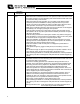
8.2 Maximum Load Be sure to check the allowable load moment. 20kg 8. Notes on Operation 10kg 8.3 How to Move the Table by Hand For the low lead types such as Lead 2 or 5, the rod will not move manually by hand. Insert a tool such as a screw driver (optional) into the cutout groove in the shaft at the rear side and twist it to move the rod.
8.4 Home return 8.4.1 Home-return Operation 1) As the motor turns, the rod returns to the negative side (actuator frame side) and contacts the mechanical stopper. Z-phase detection sensor (fixed side) Mechanical stopper Z-phase 8. Notes on Operation Encoder disk (rotating side) 2) The rod reverses and turns by rotating angle D to find encoder Z-phase.
9. 9.1 Options Changing the Connector Cable Exit Direction The standard cable exit direction is on the opposite side of the rod and guide bracket. On all models except for the slide unit type SD5N, the cable can exit from a different direction by specifying an applicable option model number, as shown below. 9.
10. Maintenance and Inspection 10.1 Inspection Items and Schedule Perform maintenance and inspection at the schedules specified below. This schedule assumes 8 hours of operations a day. If the actuator is operated continuously day and night or at a higher utilization rate, shorten the inspection intervals according to the situation.
10.3 x x x x x Cleaning Clean exterior surfaces as necessary. Use a soft cloth to wipe away dirt and buildup. Do not blow too hard with compressed air as it may cause dust to get in through the gaps. Do not use oil-based solvents as they can harm lacquered and painted surfaces. To remove severe buildup, wipe gently with a soft cloth soaked in a neutral detergent or alcohol. 10.4 Inspection of the Interior When inspecting the interior, check the items specified below.
[Internal inspection of guide rail] Actuator Guide rail V-groove (2 locations) Front Table Table Actuator Guide rail V-groove (2 locations) Rear Visually check the table and actuator’s guide rail for lubrication condition. Even when the grease is brown, the screw is lubricated property as long as the traveling surface looks wet and shining.
10.5 Internal Cleaning x Use a soft cloth to wipe away dirt and buildup. x Do not blow too hard with compressed air as it may cause dust to get in through the gaps. x Do not use oil-based solvents, neutral detergent or alcohol. 10.6 Greasing 10.6.1 Applicable Grease Lithium grease has been applied to the ball screw prior to shipment. IAI uses the following grease in our plant. Location Ball screw Supplier Kyodo Yushi Model number Maltemp LRL No. 3 10.
10.6.2 Greasing Method [How to apply grease to the ball screw] 1) Turn off the power and check the surface of the spiral cover for shavings, powder dust, etc. Use a rag, etc., to wipe off shavings, powder dust, if any. 2) Pull the table and pull the narrower end of the spiral cover toward the wider end (in the direction of the arrow) to expose the screw shaft. If the lead is too small and the table does not move, insert a slotted screwdriver, etc.
[How to apply grease for guide rail] 1) Turn off the power and pull out the table. If the lead is too small to move the table, insert a screwdriver, etc., into the cutout groove provided in the shaft on the rear side and turn. [Refer to “How to Move Table by Hand.”] Table 10. Maintenance and Inspection Actuator Guide rail V-groove (2 locations) Table Front 2) Guide rail V-groove (2 locations) Rear Wipe off the grease attached to the V-groove in the guide rail and apply the specified grease.
10.7 How to Replace the Spiral Cover [Item required for replacement] x Replacement spiral cover [Procedure] 1) Remove the spiral cover. Pull out the base of the spiral cover toward you and roll the edge of the cover. Spiral Cover 10. Maintenance and Inspection 2) Gradually roll the spiral cover to remove it. .
10. Maintenance and Inspection 3) Pull out the thin side of the replacement spiral cover and take out the end hidden inside. 4) Install the replacement spiral cover. Hook the end of the replacement spiral cover you have taken out. Once the end is hooked, orient the cover so that the end faces the inside. Roll the cover so the tip comes inside. 5) Push the end toward the shaft end while winding the cover a little.
6) Continue to wind the replacement spiral cover. 7) Finally, orient the cover so that the end faces the outside, and push the cover into the actuator groove.
4- M5 depth 12 φ5 +0.03 0 depth 5 36 16 11 26 48 6 69 71 5+0.03 0 depth 5 48 35 26 10 28 15 4-M5 depth 7 10 ME 41 40 76 φ5 +0.03 0 depth 5 12 Home 3 ST 48 +0.03 φ5 0 depth 5 4-M5 depth 8 50 L 56 M N 50 6 48 28 5 +0.03 0 depth 5 2-M4 depth 4 5 +0.03 0 depth 5 Stroke 50 75 37 L 130 155 Secure at least 150 6.5 L1 126 151 33 46 L2 108 133 M 89 105.5 6.5 Weight[kg] 1.3 1.5 2-M5 depth 10 TCA5N 10 11.1.1 6 External Dimensions 8 11.1 4.5 11. Appendix 11.
16 36 20 40 80 6 4-M5 depth 12 φ5 +0.03 0 depth 5 +0.03 Home ST 40 φ5 +0.030 depth 5 0 4-M5 depth 8 15 ME 12 10 3 48 76 4-M5 depth 8 φ5 +0.03 0 depth 5 50 M N 5 L 56 11. Appendix 5 0 depth 5 42 30 27 63 65 10 60 60 10 6 6 +0.030 depth 0 5 depth 5 5 +0.030 0 Stroke 50 75 L 130 155 Secure at least 150 L1 126 151 6 4.5 37 L2 108 133 M 89 105.5 33 68 Weight[kg] 1.7 2.0 6 4-M5 depth 10 11.1.
3 46 36 16 2- M5 depth 12 6 91 95 24 38.5 φ5 +0.030 depth 5 0 5 +0.030 depth 5 0 26 20 16 44 49 57 10 15 4-M5 depth 8 12 ME 41 48 5 40 76 +0.030 depth 0 +0.030 φ5 0 depth Home ST 3 φ5 4-M5 depth 8 M N 50 L 56 5 50 depth 5 5 +0.030 0 2-M4 depth 4 5 +0.030 depth 5 0 Secure at least 150 6 6 28 77 9 11. Appendix 8 50 Stroke 50 75 37 9 L 130 155 4.5 L1 126 151 6.5 46.5 L2 108 133 33 M 89 105.5 Weight[kg] 1.4 1.6 6.5 3-M5 depth 10 11.1.
12. Warranty 12.1 Warranty Period One of the following periods, whichever is shorter: x 18 months after shipment from IAI x 12 months after delivery to the specified location x 2,500 hours of operation 12.2 Scope of Warranty Our products are covered by warranty when all of the following conditions are met. Faulty products covered by warranty will be replaced or repaired free of charge: (1) The breakdown or problem in question pertains to our product as delivered by us or our authorized dealer.
12.5 Conditions of Conformance with Applicable Standards/Regulations, Etc., and Applications (1) If our product is combined with another product or any system, device, etc., used by the customer, the customer must first check the applicable standards, regulations and/or rules. The customer is also responsible for confirming that such combination with our product conforms to the applicable standards, etc.
Change History Revision Date Description of Revision December 2011 First edition September 2012 Second edition Additions and Changes made in Safety Guide contents in Pg.1 to 7 International Standards Compliances added in Pg.9 CE: Complied with CE Mark added to “How to Read the Model Number” option in Pg. 14 Weight added to “11.1 External Dimensions” added in Pg.
Manual No.: ME3719-2A (September 2012) Head Office: 577-1 Obane Shimizu-KU Shizuoka City Shizuoka 424-0103, Japan TEL +81-54-364-5105 FAX +81-54-364-2589 website: www.iai-robot.co.jp/ Technical Support available in USA, Europe and China Head Office: 2690 W.