
Manual

219
12. Appendix
207
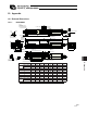
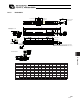
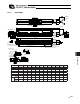
12.1.7 RCS2-SA4D
50 100 150 200 250 300
L 261 311 361 411 461 511
A 146 196 246 296 346 396
M 122 172 222 272 322 372
N 50 100 100 200 200 300
P 35 85 85 185 185 285
R 22 22 72 22 72 22
U � 1 1 2 2 3
m 4 4 4 6 6 8
Stroke
2-3H7, effective depth 5
Cable joint
connector
At least 100 or
more
Reference
surface
4-M3, depth 7
Detail view of A
Stroke
Detail view of B
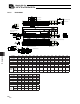
Home
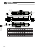
m-M3, depth 5
4-3.6
6.5, deep counterbore, depth 3.5
(for actuator installation)
Bottom
End face of base
Oblong hole, depth 5 from
bottom surface of base
Reference
position for Ma
moment offset
Brake Dimensions
R: Brake cable exit direction (right)
E: Brake cable exit direction (end)
L: Brake cable exit
direction (left)
End face of base
Detail of oblong hole
P (pitch of 3 hole and oblong hole)
N (pitch of 3 holes)
2-3H7 Oblong hole, depth 5 from
bottom surface of base
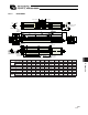
50 (stroke 50)
U x 100
P
(stroke other than 50)
(tolerance for reamed
hole pitch 0.02 mm)
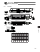
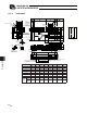
Stroke 50 100 150 200 250 300
L 261 311 361 411 461 511
A 146 196 246 296 346 396
M 122 172 222 272 322 372
N 50 100 100 200 200 300
P 35 85 85 185 185 285
R 22 22 72 22 72 22
U - 1 1 2 2 3
m 4 4 4 6 6 8
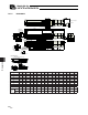
Weight
[kg]
without
brake
0.8 0.9 1.0 1.1 1.2 1.3
with
brake
1.0 1.1 1.2 1.3 1.4 1.5