
Manual

221
12. Appendix
209
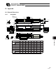
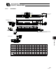
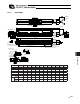
12.1.9 RCS2-SA6D
50 100 150 200 250 300 350 400 450 500 550 600
L 304.5 354.5 404.5 454.5 504.5 554.5 604.5 654.5 704.5 754.5 804.5 854.5
A 198 248 298 348 398 448 498 548 598 648 698 748
N 81 131 181 231 281 331 381 431 481 531 581 631
P 66 116 166 216 266 316 366 416 466 516 566 616
R 81 31 81 31 81 31 81 31 81 31 81 31
U 1 2 2 3 3 4 4 5 5 6 6 7
m 6 8 8 10 10 12 12 14 14 16 16 18
Stroke
2-5H7, effective depth 6
Cable joint
connector
At least 100
or more
Reference
surface
4-M5, depth 9
Stroke
Detail view of A
Home
m-M5, depth 8
Reference position for Ma
moment offset
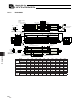
Detail of oblong hole
Oblong hole, depth 5 from bottom
surface of base
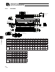
Brake Dimensions
R: Brake cable exit from right
E: Brake cable
exit from end
L: Brake cable
exit from left
3-4H7 Depth 5 from bottom surface of base
(pitch of 4 holes)
(pitch of 4 hole and oblong hole)
(pitch of 4 holes)
Bottom surface of base
(tolerance for reamed
hole pitch 0.02 mm)
End face of base
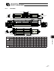
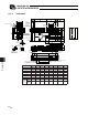
Stroke 50 100 150 200 250 300 350 400 450 500 550 600
L 304.5 354.5 404.5 454.5 504.5 554.5 604.5 654.5 704.5 754.5 804.5 854.5
A 198 248 298 348 398 448 498 548 598 648 698 748
N 81 131 181 231 281 331 381 431 481 531 581 631
P 66 116 166 216 266 316 366 416 466 516 566 616
R 81 31 81 31 81 31 81 31 81 31 81 31
U 1 2 2 3 3 4 4 5 5 6 6 7
m 6 8 8 10 10 12 12 14 14 16 16 18
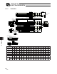
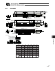
Weight
[kg]
without
brake
1.3 1.5 1.7 1.9 2.1 2.3 2.5 2.7 2.9 3.1 3.3 3.5
with
brake
1.6 1.8 2.0 2.2 2.4 2.6 2.8 3.0 3.2 3.4 3.6 3.8