
Manual

234
12. Appendix
222
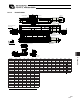
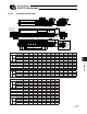
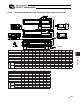
12.1.22 RCS2CR-SA5D
50 100 150 200 250 300 350 400 450 500
L 263.5 313.5 363.5 413.5 463.5 513.5 563.5 613.5 663.5 713.5
A 172 222 272 322 372 422 472 522 572 622
M 142 192 242 292 342 392 442 492 542 592
N 50 100 100 200 200 300 300 400 400 500
P 35 85 85 185 185 285 285 385 385 485
R 42 42 92 42 92 42 92 42 92 42
U � 1 1 2 2 3 3 4 4 5
m 4 4 4 6 6 8 8 10 10 12
Stroke
Opposite side
(option)
2-4H7, depth 6
Cable joint
connector
4-M4 depth 9
At least 100 or more
Home
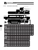
Stroke
(tolerance for reamed
hole pitch 0.02 mm)
4-4.5 through, 8 counterbore,
depth 4.5
Reference position
for Ma moment offset
End face of base
R: Brake cable exit
from right
E: Brake cable
exit from end
L: Brake cable
exit from left
Detail of oblong hole
m-M4 depth 7
Oblong hole, depth
5 from bottom
surface of base
(pitch of 4 hole and oblong hole)
(pitch of 4 holes)
End face of base
ME: Mechanical End,
SE: Stroke End
Standard side
Applicable tube outer diameter: 8
(stroke 50)
(stroke other than 50)
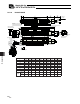
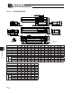
Brake Dimensions
2-4H7 Depth 5 from bottom
surface of base
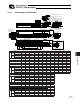
Stroke 50 100 150 200 250 300 350 400 450 500
L 263.5 313.5 363.5 413.5 463.5 613.5 563.5 613.5 663.5 713.5
A 172 222 272 322 372 422 472 522 572 622
M 142 192 242 292 342 392 442 492 542 592
N 50 100 100 200 200 300 300 400 400 500
P 35 85 85 185 185 285 285 385 385 485
R 42 42 92 42 92 42 92 42 92 42
U - 1 1 2 2 3 3 4 4 5
m 4 4 4 6 6 8 8 10 10 12
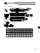
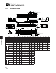
Weight
[kg]
without
brake
1.5 1.6 1.7 1.8 1.9 2.0 2.1 2.2 2.3 2.5
with
brake
1.8 1.9 2.0 2.1 2.2 2.3 2.4 2.5 2.6 2.8