
Instruction Manual


5. Modbus RTU
175
Modbus
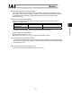
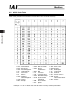
Continued from the previous page
Field
RTU mode
8-bit data
Remarks
0000
H
All upper bits of the 32-bit data are 0.
New data 7, 8
(individual zone boundary +)
Input unit (0.01 mm)
1770
H
60 (mm) x 100 = 6000 o 1770
H
0000
H
All upper bits of the 32-bit data are 0.
New data 9, 10
(individual zone boundary -)
Input unit (0.01 mm)
0FA0
H
40 (mm) x 100 = 4000 o 0FA0
H
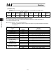
New data 11 (acceleration)
Input unit (0.01 G)
0001
H
0.01 (G) x 100 = 1 o 0001
H
New data 12 (deceleration)
Input unit (0.01 G)
001E
H
0.3 (G) x 100 = 30 o 001E
H
New data 13 (push)
Input unit (%)
0000
H
0 (%) o 0
H
New data 14 (threshold)
Input unit (%)
0000
H
0 (%) o 0
H
New data 15 (control flag) 0000
H
All bits are 0, because normal operation is specified.
0000
b
o 0000
H
Error check 701E
H
CRC check calculation result o 701E
H
End Silent interval
Total number of bytes 39
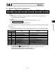
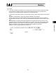
*1) Calculation of start address
In the example, all data of position No. 12 is changed. Accordingly, the target position address of
position No. 12 is set in the start address field of this query.
1000
H
+ (16 x 12 =192)
H
+ 0
H
= 1000
H
+ C0
H
+ 0
H
= 10C0
H
“10C0” becomes the input value for the start address field of this query.