
Instruction Manual


6. Modbus ASCII
179
Modbus
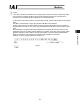
6.1 Message Frames (Query and Response)
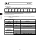
Start Address Function code Data LRC Check End
1 character 2 characters 2 characters n characters 2 characters 2 characters
1 byte 2 bytes 2 bytes nx2 bytes 2 bytes 2 bytes
* 1 character is expressed with 1 byte (2 characters) in ASCII code (refer to 6.2 ASCII “Code
Table”).
(1) Start
The Start field is equivalent to the header field and “:” (colon) is used in the ASCII mode.
It is expressed as 3A
H
in ASCII code.
(2) Address
This field specifies the addresses of connected RC controllers (01
H
to 10
H
).
Set Address = axis number + 1
in ASCII code. Example) The axis number/is 30
H
32
H
.
Note: The address is not equal to the corresponding axis number: be careful when making settings.
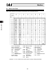
(3) Function
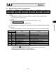
The table below summarizes the function codes and functions that can be used with RC controllers.
Code
[Hex] (ASCII)
Name Function
01
H
30
H
31
H
. Read Coil Status Read coils/DOs.
02
H
30
H
32
H
. Read Input Status Read input statuses/DIs.
03
H
30
H
33
H
. Read Holding Registers Read holding registers.
04
H
30
H
34
H
. Read Input Registers Read input registers.
05
H
30
H
35
H
. Force Single Coil Write one coil/DO.
06
H
30
H
36
H
. Preset Single Register Write holding register.
07
H
30
H
37
H
. Read Exception Status Read exception statuses.
0F
H
30
H
46
H
. Force Multiple Coils Write multiple coils/DOs at once.
10
H
31
H
30
H
. Preset Multiple Registers Write multiple holding registers at once.
11
H
31
H
31
H
. Report Slave ID Query a slave’s ID.
17
H
31
H
37
H
. Read / Write Registers Read/write registers.
* This manual uses mark function codes.
* The ROBONET gateway supports three types of function codes (03
H
, 06
H
and 10
H
).
(Refer to the separate ROBONET Instruction Manual.)
The ROBONET gateway does not support the ASCII mode.