
Instruction Manual


6. Modbus ASCII
282
Modbus
(6) Example of use
Examples of different operations are shown in [1] to [7] below.
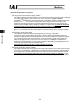
[1] Move by changing the target position. (All data other than the target position are the default
values of their respective parameters.)
Conditions: The operation conditions conform to the default speed, default
acceleration/deceleration and default positioning band set by the controller’s user
parameters. Only the target position is changed to move the actuator.
Supplement: Controller’s user parameters
x Default speed (parameter No. 8) o Maximum speed of the applicable actuator as specified
in the catalog
x Default acceleration/deceleration (parameter No. 9) o Rated acceleration of the applicable
actuator as specified in the catalog
x Default positioning band (parameter No. 10) o Default value = 0.1 mm
Write the target position specification register (9900
H
)
(Example 1)
Start of movement
(Example 1) Target position: 50 mm
Target
position
[mm]
Positioning
band
[mm]
Speed
[mm/s]
Acceleration/
deceleration
[G]
Push
[%]
Control flag
50 Need not be set.
Query : 01 10 9900 0002 04 0000 1388 B5[CR][LF]
Response : 01 10 9900 0002 54[CR][LF]
--- The query message is copied, except for the number of bytes and new data, and returned
as a response.
ᴾBreakdown of Query Message
Field ASCII mode
fixed character string
Converted ASCII
code data [H]
Remarks
Header ‘:’ 3A
Slave address ‘0’, ‘1’ 3031 Axis number + 1
Function code ‘1’, ‘0’ 3130
Start address
‘9’, ‘9’, ‘0’, ‘0’
39393030 The start address is the target position
specification register 9900
H
.
Number of registers
‘0’, ‘0’, ‘0’, ‘2’
30303032 Specify 9900
H
through 9901
H
as the
addresses to be written.
‘0’, ‘4’
3034
2 (registers) × 2 = 4 (bytes) o 4
H
Number of bytes
‘0’, ‘0’, ‘0’, ‘0’ 30303030
Changed data 2 [H]
‘1’, ‘3’, ‘8’, ‘8’
31333838
50 [mm] x 100 = 5000 o 1388
H
Error check
‘B’, ‘5’
4235
LRC checksum calculation result o B5
H
Trailer ‘CR’, ‘LF’ 0D0A
Total number of bytes 27