
Instruction Manual


6. Modbus ASCII
292
Modbus
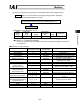
(Example 7) Change the push current limit from 70% to 50% during a push-motion operation.
Target
position
[mm]
Positioning
band
[mm]
Speed
[mm/s]
Acceleration/
deceleration
[G]
Push
[%]
Control flag
50 20 100 0.3
70 o 50
Push-motion
operation
(bit1 = 1,
bit2 = 1)
Query: 01 10 9907 0002 04 007F 0006 C4[CR][LF]
Response: 01 10 9907 0002 4D[CR][LF]
--- The query message is copied, except for the number of bytes and new data, and returned
as a response.
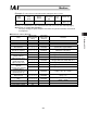
ᴾBreakdown of Query Message
Field
ASCII mode
fixed character
string
Converted
ASCII code
data [H]
Remarks
Header ‘:’ 3A
Slave address ‘0’, ‘1’ 3031 Axis No. 0 + 1
Function code ‘1’, ‘0’ 3130
Start address ‘9’, ‘9’, ‘0’, ‘7’ 39393037
The start address is the target position
specification register 9907
H
.
Number of registers ‘0’, ‘0’, ‘0’, ‘2’ 30303032
Specify 9907
H
through 9908
H
as the
addresses to be written.
Number of bytes ‘0’, ‘4’ 3034
2 (registers) x 2 = 4 (bytes) o 4
H
Changed data 8 (push)
Input unit (%)
‘0’, ‘0’, ‘7’, ‘F’ 30303746 50 [%] ĺ 7F
H
Changed data 9 (control
flag)
‘0’, ‘0’, ‘0’, ‘6’ 30303036
(Push setting)
1000b o 0006
H
Error check ‘C’, ‘4’ 4334
LRC check calculation result o C4
H
Trailer ‘CR’, ‘LF’ 0D0A
Total number of bytes 27