
Instruction Manual


4. Communication
47
Modbus
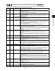
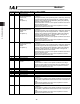
(16) Data of special port monitor registers (Address = 9012
H
) (SIPM)
Bit Symbol Name Function
15 - Cannot be used
14 NP Command pulse NP signal
status
This bit indicates the status of the command pulse NP signal.
13 - Cannot be used
12 PP Command pulse PP signal
status
This bit indicates the status of the command pulse PP signal.
11 - Cannot be used
10 - Cannot be used
9 - Cannot be used
8 MDSW Mode switch status 0: AUTO mode
1: MANU mode
This bit becomes 1 when the RC controller is in the MANU mode.
Note that the controller is always in the MANU mode in cases of models
not equipped with an operation mode switch (ERC2, PCON-SE/CY,
ACON-SE/CY).
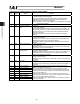
7 - Cannot be used
6 - Cannot be used
5 - Cannot be used
4 BLCT Belt breakage sensor
(SCON only)
0: Belt broken
1: Normal
3 HMCK Home-check sensor monitor 0: Sensor OFF
1: Sensor ON
On a model equipped with a home-check sensor function, this bit
indicates the status of sensor input.
It is always 0 on any other model.
2 OT Overtravel sensor monitor 0: Sensor OFF
1: Sensor ON
This bit indicates the status of the overtravel sensor signal in the encoder
connector.
It is always 0 on a model not equipped with an overtravel sensor.
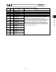
1 CREP Creep sensor monitor 0: Sensor OFF
1: Sensor ON
This bit indicates the status of the creep sensor signal in the encoder
connector.
It is always 0 on a model not equipped with a creep sensor.
0 LS Limit sensor monitor 0: Sensor OFF
1: Sensor ON
This bit indicates the status of the limit sensor signal in the encoder
connector.
It is always 0 on a model not equipped with a limit sensor.