
Instruction Manual


5. Modbus RTU
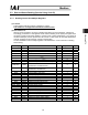
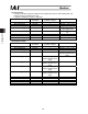
67
Modbus
(4) Query sample
A sample query that reads the contents of last occurred alarm (addresses 0500
H
to 0505
H
) of a
controller with axis No. 0 is shown below.
z Query (silent intervals are inserted before and after the query)
01 03 05 00 00 06 C5 04
Field RTU mode
8-bit data
Start Silent interval
Slave address [H] 01
Function code [H] 03
Start address [H] 0500
Number of registers [H] 0006
Error check [H] C504 (in accordance with
CRC calculation)
End Silent interval
The response to the query is as follows.
z Response (silent intervals are inserted before and after the response)
01 03 0C 00 00 FF FF 00 00 00 E8 17 2C 64 3F 2D CD
Field RTU mode
8-bit data
Start Silent interval
Slave address [H] 01
Function code [H] 03
Number of data bytes [H] 0C (12 bytes = 6 registers)
Data 1 [H] 00 00 (Alarm detail code)
Data 2 [H] FF FF (Alarm address)
Data 3 [H] 00 00 00 E8 (Alarm code)
Data 4 [H] 17 2C 64 3F (Alarm occurrence time)
Error check [H]
2DCD (in accordance with CRC calculation)
End Silent interval
Alarm detail code: 0000
H
xxxxNo detail code
Alarm address: FFFF
H
xxxDisable (no detail code)
Alarm code: 00E8
H
=0E8xxxEncoder AB phase break error
Alarm occurrence time: 172C643F
H
(conversion) 2012/04/26 19:53:35 [Conversion is
refer to the Section 4.3.2(3)]
Note 1 The data of the response example is simply an example and will vary depending on
various conditions.
Note 2 For the detail of an alarm code, check in the instruction manual of the each
controller.