Ethernet Operation Manual Third Edition
Please Read Before Use Thank you for purchasing our product. This Operation Manual explains the handling methods, structure and maintenance of this product, among others, providing the information you need to know to use the product safely. Before using the product, be sure to read this manual and fully understand the contents explained herein to ensure safe use of the product. The CD that comes with the product contains operation manuals for IAI products.
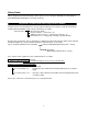
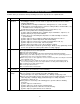
Table of Contents Safety Guide 1 1. Overview 9 2. Interface Specifications 11 3. Interface Board 12 3.1 Name of Each Part 12 3.2 Monitor LED Indications 13 4. 5. 6. 7. Remote I/O (Modbus/TCP EtherNet/IP) 14 4.1 Setup of Ethernet Environment 14 4.2 Remote I/O Setup Procedure 15 4.3 Setup Procedure for Exception Status Support 17 4.4 Correspondence of Modbus/TCP Address and X-SEL I/O 18 4.5 Installation to a Modbus/TCP System 23 4.
Safety Guide When designing and manufacturing a robot system, ensure safety by following the safety Guidess provided below and taking the necessary measures. Regulations and Standards Governing Industrial Robots Safety measures on mechanical devices are generally classified into four categories under the International Industrial Standard ISO/DIS 12100, “Safety of machinery,” as follows: Safety measures Inherent safety design Protective guards --- Safety fence, etc.
Requirements for Industrial Robots under Ordinance on Industrial Safety and Health Work area Outside movement range Inside movement range Work condition Cutoff of drive source Measure Signs for starting operation During automatic Not cut off Installation of railings, enclosures, operation etc. Cut off (including Sign, etc., indicating that work is in stopping of operation) progress Preparation of work rules Measures to enable immediate stopping of operation During teaching, etc. Sign, etc.
Applicable Models of IAI’s Industrial Robots Machines meeting the following conditions are not classified as industrial robots according to Notice of Ministry of Labor No. 51 and Notice of Ministry of Labor/Labor Standards Office Director (Ki-Hatsu No.
Notes on Safety of Our Products Common items you should note when performing each task on any IAI robot are explained below. No. Task 1 Model selection 2 Note This product is not planned or designed for uses requiring high degrees of safety. Accordingly, it cannot be used to sustain or support life and must not be used in the following applications: [1] Medical devices relating to maintenance, management, etc.
4 Installation/ startup (2) Wiring the cables Use IAI’s genuine cables to connect the actuator and controller or connect a teaching tool, etc. Do not damage, forcibly bend, pull, loop round an object or pinch the cables or place heavy articles on top. Current leak or poor electrical continuity may occur, resulting in fire, electric shock or malfunction. Wire the product correctly after turning off the power.
6 Confirmation operation 7 Automatic operation 8 Maintenance/ inspection 9 Modification 10 Disposal After teaching or programming, carry out step-by-step confirmation operation before switching to automatic operation. When carrying out confirmation operation inside the safety fences, follow the specified work procedure just like during teaching. When confirming the program operation, use the safety speed. Failure to do so may result in an unexpected movement due to programming errors, etc.
Indication of Cautionary Information The operation manual for each model denotes safety Guides under “Danger,” “Warning,” “Caution” and “Note,” as specified below. Level Degree of danger/loss Symbol Danger Failure to observe the instruction will result in an imminent danger leading to death or serious injury. Danger Warning Failure to observe the instruction may result in death or serious injury. Warning Caution Failure to observe the instruction may result in injury or property damage.
-8-
1. Overview This option allows the X-SEL controller to perform control in an open network environment using the Ethernet infrastructure, the de-facto standard and most common form of communication media for linking PCs and host computers. (1) Remote I/O control (Modbus/TCP EtherNet/IP) The X-SEL controller supports remote I/O control (a maximum of 256 input points and 256 output points) via Modbus/TCP. Modbus/TCP is an Ethernet application of the Modbus protocol used in serial communication.
A hierarchy of the functions provided by the X-SEL Ethernet option is shown below. Functions are selected by parameters. Additionally, the network environment parameters must be set.
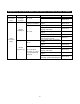
Interface Specifications Item Specification Network 10BASE-T/100BASE-T (Auto-negotiation) specification Communication IEEE802.3 standard Communication 10/100 Mbps (Auto-negotiation) speed Protocol Remote I/O Open Modbus/TCP EtherNet/IP TCP/IP message communication Class 1 Cyclic 1. IAI protocol B/TCP communication 2.
3. Interface Board 3.1 Name of Each Part Communication connector DIP switches Monitor LEDs S1 /S0 NS /MS (Note) The DIP switches are used to set the least significant byte of the IP address. With the X-SEL system, however, the IP address is set by a controller parameter without the use of DIP switches. Set all switches to OFF. (Setting the switches in any other pattern will have no effect.
3.2 Monitor LED Indications The operating condition of the interface board and its connection status to Ethernet can be checked via the four LEDs provided on the front panel of the interface board. * The LED indications of operating condition and connection condition vary between Modbus/TCP and EtherNet/IP.
Remote I/O (Modbus/TCP EtherNet/IP) 4. 4.1 Setup of Ethernet Environment The X-SEL controller provides IP addresses and other network-definition areas in its I/O parameters for control of Modbus/TCP EtherNet/IP operation. Set the necessary parameters according to the network environment before connecting to the network. Establishing a connection without setting the parameters may disable normal communication to and from other devices on the network.
4.2 Remote I/O Setup Procedure The system is configured only with the remote I/Os of Modbus/TCP EtherNet/IP, with the I/O port numbers being specified according to fixed port assignment. 4.2.
4.2.2 Combined Use of Expansion I/O Board (Modbus/TCP EtherNet/IP + Expanded I/O) The following settings are applicable when the standard I/O ports are mapped on Modbus/TCP EtherNet/IP (input-port start No. 0 and output-port start No. 300), while the expansion I/O boards are used with port assignments starting with input-port start No. 200 and output-port start No. 500. [I/O parameters] No.
4.3 Setup Procedure for Exception Status Support The X-SEL Ethernet option supports the function that notifies the host of an error condition (the upper two digits of the error number) of the X-SEL controller using an exception code stored in Modbus/TCP. By setting bits 0 to 3 of I/O parameter No. 129 to “2” (HEX), any error occurring in the X-SEL controller can be indicated to the host controller via Modbus/TCP.
4.4 Correspondence of Modbus/TCP Address and X-SEL I/O Modbus/TCP can address the same object using either bit addressing or word addressing. The DI area (bit numbers from No. 0 up to No. 299 can be defined) of the X-SEL controller is mapped in the word address 0x400 (1024) (coil and holding register as viewed from the PC side) under Modbus/TCP. The DO area (bit numbers from No. 300 up to No.
4.4.1 Little Endian Operation The default endian mode of DI/DO operation commands of the X-SEL controller is the little endian. In the little endian mode, the remote I/O field accessed via word operation with an IN, INB, OUT or OUTB command of the X-SEL controller will have its upper and lower bytes reversed in relation to the X-SEL data if the same field is word-accessed via Modbus/TCP.
[Modbus/TCP output areas (assignment of X-SEL DI area 300 onward), FMIO = 0] BIT7 (MSB) 7 16384 6 5 6 16385 5 16386 1 2 3 15 16392 14 16393 13 16394 9 10 11 X-SEL DI Modbus/TCP bit address Modbus/TCP word address Modbus output coil Modbus hold register 247 16624 246 16625 245 16626 241 242 243 X-SEL DI Modbus/TCP bit address Modbus/TCP word address Modbus output coil Modbus hold register 255 16632 254 16633 253 16634 249 250 251 Address X-SEL DI Modbus/TCP bit address Modbus/TCP
4.4.2 Big Endian Operation To align the word handling between Modbus/TCP and the X-SEL controller, the I/O operation mode must be set to the big endian with an FMIO command before executing a DI/DO operation command in any X-SEL task. With this setting the remote I/O field accessed via word operation with an IN, INB, OUT or OUTB command of the X-SEL controller can be handled as the same data when the same field is word-accessed via Modbus/TCP.
[Modbus/TCP output areas (assignment of X-SEL DI area 300 onward), FMIO = 0] BIT7 (MSB) 7 16384 6 5 6 16385 5 16386 1 2 3 15 16392 14 16393 13 16394 9 10 11 X-SEL DI Modbus/TCP bit address Modbus/TCP word address Modbus output coil Modbus hold register 247 16624 246 16625 245 16626 241 242 243 X-SEL DI Modbus/TCP bit address Modbus/TCP word address Modbus output coil Modbus hold register 255 16632 254 16633 253 16634 249 250 251 Address X-SEL DI Modbus/TCP bit address Modbus/TCP
4.5 Installation to a Modbus/TCP System No special tools are required for operation of the X-SEL controller via Modbus/TCP on Ethernet. Simply set the controller parameters, connect the Ethernet cable and turn on the power. The Modbus/TCP server in the controller will be started, enabling remote I/O control. The Ethernet port number of Modbus/TCP is fixed at “502.
5. IAI Protocol B/TCP This protocol uses TCP packets embedded with the message format of IAI protocol B for serial communication. The controller supports the slaves under this protocol, regardless of the connection method (client or server). (The connected device always becomes the protocol master.) 5.1 Setup of Ethernet Environment The X-SEL controller provides IP addresses and other network-definition areas in its I/O parameters for control of the IAI protocol B/TCP operation.
[I/O parameters] No.
0~255 141 Default gateway (MH) 0 0~255 142 Default gateway (ML) 0 0~255 143 Default gateway (L) 0 0~255 149 150 151 152 IAI protocol B/TCP: IP address of connection destination (MANU mode) (H) IAI protocol B/TCP: IP address of connection destination (MANU mode) (MH) IAI protocol B/TCP: IP address of connection destination (MANU mode) (ML) IAI protocol B/TCP: IP address of connection destination (MANU mode) (L) IAI protocol B/TCP: Port 153 number of connection destination (MANU mode) 154 155
4. One of the two ports will be used for connection, depending on the MANU/AUTO mode. 5. The port will be enabled at the following intervals: When the initialization after power ON reset is complete When no IAI protocol serial-communication message has been received for approximately five seconds after the completion of controller initialization 6.
5.2 5.2.1 Ethernet Connection of X-SEL PC Software Software Versions Supporting This Function (1) PC software 5.2.2 V2.1.0.0 or later (Japanese version) V2.1.0.0E or later (English version) Function (1) Connection confirmation a. Selecting the communication port Select “Ethernet” in the port name list on the Connection Confirmation screen. * Refer to (3) of 5.2.3, “Items to Note,” for details. Figure 1 b.
c. Selecting the controller Entering the port number and clicking the [OK] button switches the display to the Select Controller screen. Figure 3 Each time a connection is established from a controller, the IP address of the connecting controller is added to the list. Select the IP address of the controller with which you want to communicate, and then click the [OK] button. Communication will be established with the selected controller and the application will start in the online mode.
(2) Connection destination change Select “Controller (C)” “Request Release Pause (L)” from the menu. * This menu item will be added only when connections have been established from two or more controllers. Figure 4 Select the IP address of the controller with which you want to communicate, and then click the [OK] button. Communication will be established with the selected controller.
5.2.3 Items to Note (1) When connecting via Ethernet, the IP address parameter must be set via serial connection beforehand in accordance with the applicable environment. (2) If a firewall (including the firewall function of virus protection software) is installed in the PC, etc., the port block must be canceled or the firewall function disabled before a connection can be made. (This is because the very purpose of firewall software is to block external connection to the protecting device.
6. Transmission by SEL Program Four channels of ASCII-based, delimiter-controlled communication (CH31 through CH34) are supported, using a set of transmission commands in a system roughly equivalent to that used in the X-SEL controller’s serial communication. (The specification of each SEL command may vary slightly from the corresponding command specification in serial communication, so exercise due caution.) 6.
[I/O parameters] Parameter name 124 Network attribute 5 No.
134 Own IP address (ML) 0 0~255 135 Own IP address (L) 1 1~254 255 255 255 0 0 0 0 0 0~255 0~255 0~255 0~255 0~255 0~255 0~255 0~255 136 Subnet mask (H) 137 Subnet mask (MH) 138 Subnet mask (ML) 139 Subnet mask (L) 140 Default gateway (H) 141 Default gateway (MH) 142 Default gateway (ML) 143 Default gateway (L) - 34 - * Setting of “0” and “255” is prohibited.
6.2 Ethernet Option SEL Commands * The “Ethernet Option SEL Commands” are supported in the following versions: X-SEL (Cartesian) Main Application V0.79 or later X-SEL (IX SCARA) Main Application V0.29 or later X-SEL PC Software Ver. 2.1.1.
(Note 8) The diagram below explains the mechanism of “socket interface.” * Bear in mind that “socket,” “connect,” “write,” “read,” “close,” “bind,” “listen” and “accept” are not SEL language commands (SEL commands). (1) Client open (OPEN command) socket Generation of socket connect Establishment of connection Y close Error? N Decide whether to execute retry or perform error handling in accordance with the system.
[Example] LET LET LET LET LET IPCN SCHA OPEN TRAN N 990 GOTO 90 91 92 93 94 31 10 31 1 15 192 168 72 101 64514 90 990 99 IP address of connection destination (H) = 192 IP address of connection destination (MH) = 168 IP address of connection destination (ML) = 72 IP address of connection destination (L) = 101 Port number of connection destination = 64514 Declare the IP address/port number storage area for the connection destination of channel 31 = Local integer variable between 90 and 94.
50~: Device error information 50 51 52 53 54 55 56 57 58 59 60~64 101 102 103 104 105 106 107 108 109 110 111 112~115 116 117 118 119 121 122 123 124 125 126 127 128 Invalid Message ID Invalid Message Type Invalid Command Invalid Data Size Invalid Frame Count Invalid Frame Number Invalid Offset Invalid Address Invalid Response Flash Config Error Invalid To Be Defined 1-7 Invalid IP-address or Subnet mask Invalid socket type No free socket Invalid socket Not connected Command failed Invalid data size Inval
CLOS (Channel close) [* When the Ethernet option is used] Extension condition Input condition (I/O, flag) (LD, A, O, AB, OB) Optional Optional Command, declaration Command, Operand 1 Operand 2 declaration Channel CLOS Prohibited number Output (Output, flag) CC [Function] Close the channel specified in operand 1. Transmission via the specified channel will hereafter be disabled. (Note 1) Channel Nos. 31 through 34 can be specified in operand 1 with the Ethernet option.
READ (Read) [* When the Ethernet option is used] Extension condition Input condition (I/O, flag) (LD, A, O, AB, OB) Optional Optional Command, declaration Command, Operand 1 Operand 2 declaration Channel Column READ number number Output (Output, flag) CC [Function] Read a character string from the channel specified in operand 1 to the column specified in operand 2. The reading will end upon reaching the character specified with an SCHA command. Either a local or global column may be specified.
WRIT (Write) [* When the Ethernet option is used] Extension condition Input condition (I/O, flag) (LD, A, O, AB, OB) Optional Optional Command, declaration Command, Operand 1 Operand 2 declaration Channel Column WRIT number number Output (Output, flag) CC [Function] Write a character string from the column specified in operand 2 to the channel specified in operand 1. The writing will end when the character specified with an SCHA command is written.
IPCN (IP address/port number settings of connection destination) [* When the Ethernet option is used] Extension condition Input condition (I/O, flag) (LD, A, O, AB, OB) Optional [Function] Optional Output (Output, flag) CP Set the storage areas of IP address/port number for the connection destination of the user-open TCP/IP channel.
7. Common Items to Note (Be Sure to Read This Section.) (1) The Ethernet option will be enabled when a reset is executed on the controller equipped with an Ethernet interface board, following a parameter setup (Ethernet option function-selection parameter and network environment parameters) by transferring the parameters to the controller and writing them to the flash ROM, and an Ethernet cable connection.
(9) If a firewall (including the firewall function of virus protection software) is installed in the PC, etc., the port block must be canceled or the firewall function disabled before a connection can be made. (This is because the very purpose of firewall software is to block external connection to the protecting device.) (10) When the Ethernet option is enabled, the system will detect a “link error” if the connection is not made using the correct Ethernet cable. Set “I/O parameter No.
Appendix: X-SEL (Cartesian/IX SCARA) Ethernet Option Parameters [I/O parameters] Setting requirement A: Required (function selection) B: Required (network environment, etc.) C: Checked (As a rule, the default value on the parameter list must be used.) Modbus/ IAI protocol Transmission by TCP B/TCP SEL program No.
Setting requirement A: Required (function selection) B: Required (network environment, etc.) C: Checked (As a rule, the default value on the parameter list must be used.) Modbus/ IAI protocol Transmission by TCP B/TCP SEL program No.
Setting requirement A: Required (function selection) B: Required (network environment, etc.) C: Checked (As a rule, the default value on the parameter list must be used.) Modbus/ IAI protocol Transmission by TCP B/TCP SEL program C A C A No.
Setting requirement A: Required (function selection) B: Required (network environment, etc.) C: Checked (As a rule, the default value on the parameter list must be used.) Modbus/ IAI protocol Transmission by TCP B/TCP SEL program No.
Setting requirement A: Required (function selection) B: Required (network environment, etc.) C: Checked (As a rule, the default value on the parameter list must be used.) Modbus/ IAI protocol Transmission by TCP B/TCP SEL program No.
Setting requirement A: Required (function selection) B: Required (network environment, etc.) C: Checked (As a rule, the default value on the parameter list must be used.) Modbus/ IAI protocol Transmission by TCP B/TCP SEL program No.
Setting requirement A: Required (function selection) B: Required (network environment, etc.) C: Checked (As a rule, the default value on the parameter list must be used.) Modbus/ IAI protocol Transmission by TCP B/TCP SEL program B C No. Parameter name 158 IAI protocol B/TCP: Port number of connection destination (AUTO mode) 159 IAI protocol B/TCP: Own port number (AUTO mode) Default value (reference) 64611 Input range Unit * In the server mode “0” can be set.
Catalog No.: ME0140-3A Head Office: 2690 W. 237th Street, Torrance, CA 90505 TEL (310) 891-6015 FAX (310) 891-0815 Chicago Office: 1261 Hamilton Parkway, Itasca, IL 60143 TEL (630) 467-9900 FAX (630) 467-9912 Atlanta Office: 1220 Kennestone Circle, Suite 108, Marietta, GA 30066 TEL (678) 354-9470 FAX (678) 354-9471 website: www.intelligentactuator.com Ober der Röth 4, D-65824 Schwalbach am Taunus, Germany TEL 06196-88950 FAX 06196-889524 IAI (Shanghai) Co., Ltd.